## Diagram: Recurrent Neural Network Architecture
### Overview
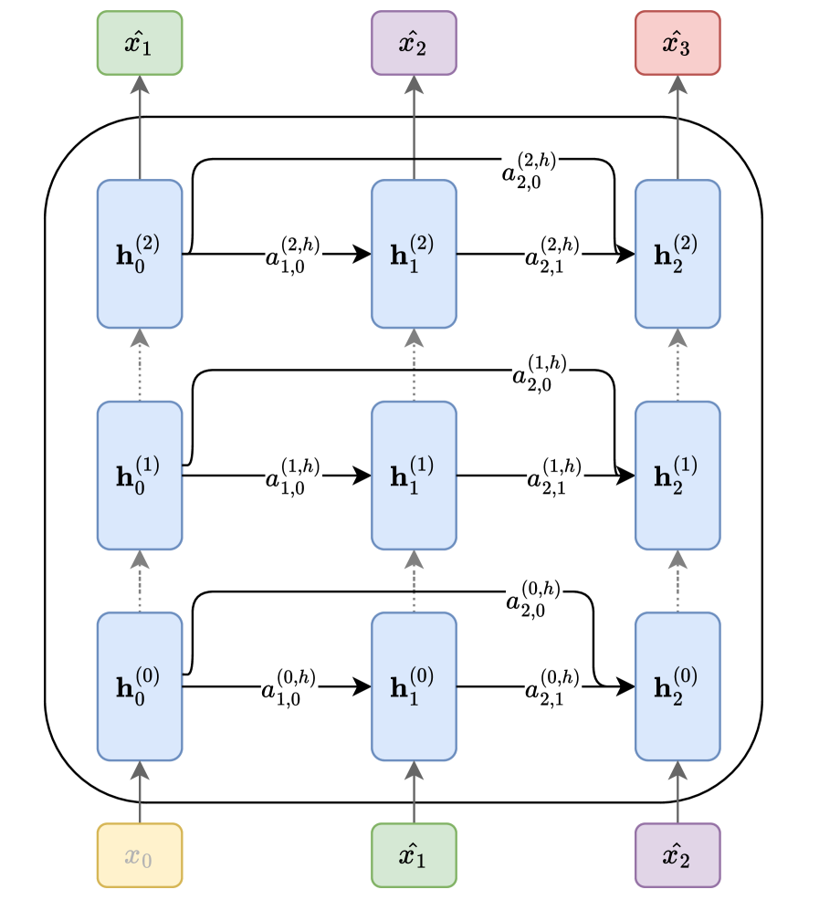
The image depicts a recurrent neural network (RNN) architecture with three layers and three time steps. It illustrates the flow of information between hidden states and input/output nodes. The diagram highlights the recurrent connections within each layer and the connections between layers.
### Components/Axes
* **Nodes:**
* Input nodes: x₀ (yellow), x̂₁ (green), x̂₂ (purple) at the bottom.
* Output nodes: x̂₁ (green), x̂₂ (purple), x̂₃ (red) at the top.
* Hidden state nodes: h₀⁽⁰⁾, h₁⁽⁰⁾, h₂⁽⁰⁾, h₀⁽¹⁾, h₁⁽¹⁾, h₂⁽¹⁾, h₀⁽²⁾, h₁⁽²⁾, h₂⁽²⁾ (all light blue).
* **Connections:**
* Vertical dotted arrows: Represent connections between layers at the same time step.
* Horizontal solid arrows: Represent recurrent connections within the same layer.
* Solid arrows from input nodes to the first layer of hidden states.
* Solid arrows from the last layer of hidden states to the output nodes.
* **Labels:**
* a₁,(i,h) labels the horizontal arrows from left to center
* a₂,(i,h) labels the horizontal arrows from center to right
* a₂,(i,0) labels the curved arrows from left to right
### Detailed Analysis
* **Layer 0 (Bottom):**
* Input: x₀ (yellow) connects to h₀⁽⁰⁾.
* Hidden states: h₀⁽⁰⁾ connects to h₁⁽⁰⁾ via a₁,(0,h), and h₁⁽⁰⁾ connects to h₂⁽⁰⁾ via a₂,(0,h).
* h₀⁽⁰⁾ connects to h₀⁽¹⁾ in the layer above via a dotted arrow.
* h₁⁽⁰⁾ connects to h₁⁽¹⁾ in the layer above via a dotted arrow.
* h₂⁽⁰⁾ connects to h₂⁽¹⁾ in the layer above via a dotted arrow.
* **Layer 1 (Middle):**
* Hidden states: h₀⁽¹⁾ connects to h₁⁽¹⁾ via a₁,(1,h), and h₁⁽¹⁾ connects to h₂⁽¹⁾ via a₂,(1,h).
* h₀⁽¹⁾ connects to h₀⁽²⁾ in the layer above via a dotted arrow.
* h₁⁽¹⁾ connects to h₁⁽²⁾ in the layer above via a dotted arrow.
* h₂⁽¹⁾ connects to h₂⁽²⁾ in the layer above via a dotted arrow.
* **Layer 2 (Top):**
* Hidden states: h₀⁽²⁾ connects to h₁⁽²⁾ via a₁,(2,h), and h₁⁽²⁾ connects to h₂⁽²⁾ via a₂,(2,h).
* Output: h₀⁽²⁾ connects to x̂₁ (green), h₁⁽²⁾ connects to x̂₂ (purple), and h₂⁽²⁾ connects to x̂₃ (red).
* **Recurrent Connections:**
* h₀⁽⁰⁾ connects to h₂⁽¹⁾ via a curved arrow labeled a₂,(0,0).
* h₀⁽¹⁾ connects to h₂⁽²⁾ via a curved arrow labeled a₂,(1,0).
* h₀⁽²⁾ connects to h₂⁽²⁾ via a curved arrow labeled a₂,(2,0).
* **Input/Output Mapping:**
* x₀ (yellow) -> h₀⁽⁰⁾ -> ... -> x̂₁ (green)
* x̂₁ (green) -> h₁⁽⁰⁾ -> ... -> x̂₂ (purple)
* x̂₂ (purple) -> h₂⁽⁰⁾ -> ... -> x̂₃ (red)
### Key Observations
* The diagram illustrates a typical RNN architecture with recurrent connections within each layer and connections between layers.
* The hidden states at each time step are influenced by the input at that time step and the hidden state from the previous time step.
* The output at each time step is determined by the hidden state at that time step.
* The diagram shows a three-layer RNN, but the architecture can be extended to more layers.
* The diagram shows a three-time-step RNN, but the architecture can be extended to more time steps.
### Interpretation
The diagram represents a simplified view of a recurrent neural network. The RNN processes sequential data by maintaining a hidden state that is updated at each time step. The recurrent connections allow the network to "remember" information from previous time steps, which is crucial for tasks such as natural language processing and time series analysis. The diagram highlights the key components of an RNN, including the input nodes, hidden states, output nodes, and connections between them. The recurrent connections enable the network to learn complex patterns in sequential data. The connections between layers allow the network to extract hierarchical features from the input data. The diagram provides a visual representation of the flow of information through the network, which can be helpful for understanding how RNNs work.