## Diagram: Approximate Processing-in-Memory Architecture
### Overview
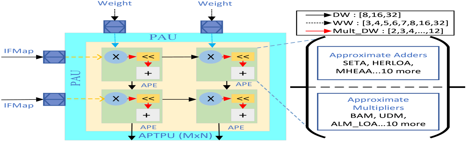
The image presents a diagram of an Approximate Processing-in-Memory (APiM) architecture. It illustrates the flow of data through Processing Array Units (PAUs) containing Approximate Processing Elements (APEs). The diagram also highlights the use of approximate adders and multipliers within the architecture.
### Components/Axes
* **Inputs:**
* `IFMap` (Input Feature Map): Two inputs labeled "IFMap" enter from the left, feeding into the PAU.
* `Weight`: Two inputs labeled "Weight" enter from the top, feeding into the PAU.
* **Processing Units:**
* `PAU` (Processing Array Unit): A light blue box containing the APEs.
* `APE` (Approximate Processing Element): Green boxes containing a multiplier, a shift operation, and an adder.
* `APTPU (MxN)`: Approximate Tensor Processing Unit, the overall architecture.
* **Operations:**
* `X`: Multiplication operation.
* `<<`: Shift operation.
* `+`: Addition operation.
* **Legend (Top-Right):**
* `DW`: Solid black line with an arrow, associated with the values `[8, 16, 32]`.
* `WW`: Dashed black line with an arrow, associated with the values `[3, 4, 5, 6, 7, 8, 16, 32]`.
* `Mult_DW`: Solid red line with an arrow, associated with the values `[2, 3, 4, ..., 12]`.
* **Approximate Components (Right):**
* `Approximate Adders`: Listed as "SETA, HERLOA, MHEAA...10 more".
* `Approximate Multipliers`: Listed as "BAM, UDM, ALM_LOA...10 more".
### Detailed Analysis
* **Data Flow:** The `IFMap` inputs enter the PAU and are processed by the APEs. The `Weight` inputs also feed into the PAU. Within each APE, the data undergoes multiplication, a shift operation, and addition. The output of each APE feeds into the next, and the final output goes to the `APTPU (MxN)`.
* **PAU Structure:** The PAU consists of a 2x2 grid of APEs. Each APE contains a multiplier (X), a shift operation (<<), and an adder (+).
* **Legend Interpretation:**
* The `DW` (Data Width) parameter takes values of 8, 16, or 32.
* The `WW` (Weight Width) parameter takes values from 3 to 8, and also 16 and 32.
* The `Mult_DW` (Multiplier Data Width) parameter takes values from 2 to 12.
* **Approximate Components:** The diagram highlights that approximate adders and multipliers are used within the architecture. Specific examples of approximate adders include SETA, HERLOA, and MHEAA. Examples of approximate multipliers include BAM, UDM, and ALM_LOA. The "...10 more" indicates that there are at least 10 other approximate adders and multipliers used.
### Key Observations
* The architecture utilizes approximate computing techniques to reduce power consumption and improve performance.
* The PAU is the core processing unit, containing multiple APEs.
* The diagram emphasizes the use of approximate adders and multipliers as key components of the architecture.
### Interpretation
The diagram illustrates a hardware architecture designed for efficient processing of data using approximate computing. The use of approximate adders and multipliers allows for trade-offs between accuracy and performance, potentially leading to significant improvements in energy efficiency. The PAU structure suggests a parallel processing approach, where multiple APEs operate simultaneously to accelerate computation. The diagram highlights the key components and data flow within the architecture, providing a high-level overview of its functionality. The architecture is likely intended for applications where some degree of error is tolerable in exchange for improved performance and energy efficiency, such as image processing or machine learning.