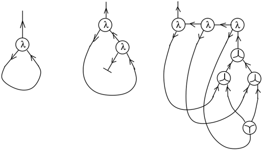
## State Transition Diagrams: System Behavior Representation
### Overview
The image contains three progressively complex state transition diagrams, each illustrating system behavior through labeled nodes (circles) and directional arrows. The diagrams use the Greek letter λ (lambda) to denote states and arrows to represent transitions, with variations in arrow style indicating different transition types.
### Components/Axes
- **Nodes**:
- All nodes are labeled with the symbol λ (lambda), representing generic states.
- Nodes are depicted as circles, with some containing internal symbols (e.g., a three-pronged fork).
- **Arrows**:
- Standard arrows (→) indicate unidirectional transitions.
- Bidirectional arrows (↔) suggest reversible transitions.
- A T-shaped arrow (↑↓) appears in Diagram 2, possibly denoting a conditional or hierarchical transition.
- Loops (arrows returning to the same node) are present in all diagrams.
- **Internal Symbols**:
- A three-pronged fork () appears in Diagram 3, potentially representing a branching or parallel process.
### Detailed Analysis
#### Diagram 1 (Left)
- **Structure**: A single λ node with:
- An upward-pointing arrow (↑) from an external source to the node.
- A self-loop (→) from the node to itself.
- **Interpretation**: Represents a system with one state that can transition to itself (loop) and receives input from an external source (↑).
#### Diagram 2 (Center)
- **Structure**: Two λ nodes connected by:
- A bidirectional arrow (↔) between them.
- A T-shaped arrow (↑↓) from the top node to the bottom node.
- A self-loop on the bottom node.
- **Interpretation**: Models a two-state system with mutual transitions (↔) and a conditional or prioritized transition (↑↓) from State A to State B. The self-loop on State B suggests persistence in that state.
#### Diagram 3 (Right)
- **Structure**: Four λ nodes with:
- Multiple bidirectional (↔) and unidirectional (→) arrows.
- A three-pronged fork () in one node, splitting into three outgoing arrows.
- A loop on the bottom-right node.
- **Interpretation**: Depicts a complex system with parallel processes (), feedback loops, and conditional transitions. The fork suggests divergence into multiple pathways, while loops indicate cyclical behavior.
### Key Observations
1. **Scaling Complexity**: Diagrams increase in complexity from left to right, suggesting a progression from simple to advanced system modeling.
2. **Symbol Consistency**: The λ label is uniformly used across all diagrams, implying a shared context (e.g., states in a computational or physical system).
3. **Arrow Variants**: The introduction of T-shaped and forked arrows in later diagrams indicates expanded transition semantics (e.g., conditions, parallelism).
### Interpretation
These diagrams likely represent state machines or process flows in a technical system (e.g., software, hardware, or workflow). The use of λ as a generic state label suggests abstraction, allowing application to diverse domains. The progression from single-state to multi-state systems with branching and loops highlights increasing behavioral complexity. The T-shaped and forked arrows imply conditional logic or concurrency, critical for modeling real-world systems where transitions depend on external inputs or internal states.
No numerical data, charts, or textual content in other languages are present. The diagrams focus purely on structural and transitional relationships.