## System Block Diagram: Speed Estimation and Braking Control
### Overview
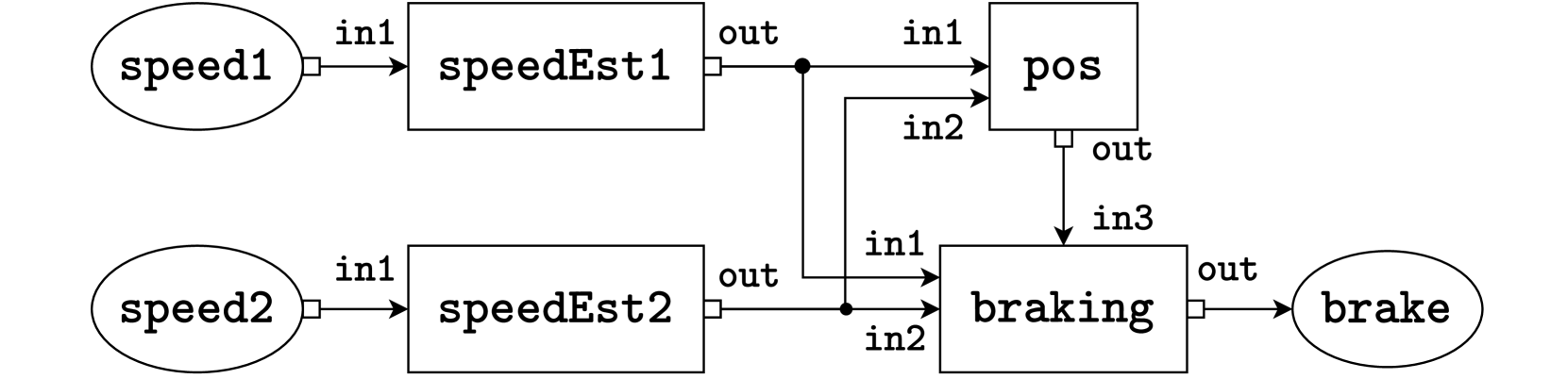
The image displays a technical block diagram representing a control system for speed estimation and braking. The diagram illustrates the flow of signals from two speed inputs, through estimation and processing blocks, to a final braking output. It is a functional schematic, not a data chart, so no numerical values or trends are present. The structure suggests a redundant or dual-channel system for safety-critical applications.
### Components/Axes
The diagram consists of the following components, connected by labeled signal lines:
**Input Sources (Ovals, Left Side):**
* `speed1` (Top-left oval)
* `speed2` (Bottom-left oval)
**Processing Blocks (Rectangles, Center):**
* `speedEst1` (Top-center rectangle)
* `speedEst2` (Bottom-center rectangle)
* `pos` (Top-right rectangle)
* `braking` (Bottom-right rectangle)
**Output Sink (Oval, Right Side):**
* `brake` (Far-right oval)
**Signal Connections (Labeled Lines):**
* From `speed1` to `speedEst1`: Labeled `in1`
* From `speed2` to `speedEst2`: Labeled `in1`
* From `speedEst1` to `pos`: Labeled `out` (from speedEst1) to `in1` (of pos)
* From `speedEst1` to `braking`: Labeled `out` (from speedEst1) to `in1` (of braking)
* From `speedEst2` to `pos`: Labeled `out` (from speedEst2) to `in2` (of pos)
* From `speedEst2` to `braking`: Labeled `out` (from speedEst2) to `in2` (of braking)
* From `pos` to `braking`: Labeled `out` (from pos) to `in3` (of braking)
* From `braking` to `brake`: Labeled `out`
### Detailed Analysis
The system architecture is as follows:
1. **Input Stage:** Two independent speed signals (`speed1`, `speed2`) are provided.
2. **Estimation Stage:** Each speed signal is processed by its own dedicated estimator block (`speedEst1`, `speedEst2`). The output of each estimator is a single signal.
3. **Processing & Fusion Stage:**
* The `pos` block receives both estimated speed signals (`in1` from `speedEst1`, `in2` from `speedEst2`). Its function is likely to calculate a position or a fused speed/position metric.
* The `braking` control block is the central decision unit. It receives three inputs: the two raw estimated speeds (`in1` from `speedEst1`, `in2` from `speedEst2`) and the processed output from the `pos` block (`in3`).
4. **Output Stage:** The `braking` block generates a single control signal (`out`) that is sent to the final actuator or system labeled `brake`.
### Key Observations
* **Redundancy:** The system uses two parallel speed estimation channels (`speedEst1` and `speedEst2`), which is a common design pattern for fault tolerance and reliability in safety-critical systems (e.g., automotive, aerospace).
* **Signal Routing:** The output of `speedEst1` is routed to two different downstream blocks (`pos` and `braking`). Similarly, the output of `speedEst2` is also routed to both `pos` and `braking`.
* **Hierarchical Control:** The `braking` block integrates information from three distinct sources: the two direct speed estimates and a derived metric from the `pos` block. This suggests a sophisticated control algorithm that considers multiple factors before issuing a brake command.
* **Unidirectional Flow:** All signal arrows point from left to right, indicating a feed-forward control system with no visible feedback loops in this diagram.
### Interpretation
This block diagram represents the logical architecture of a **dual-redundant speed-sensing and braking control system**. The primary purpose is to generate a reliable `brake` command based on multiple, independently derived speed measurements.
* **What it demonstrates:** The system prioritizes reliability and fault detection. By having two separate speed estimators, the system can potentially cross-check their outputs. If one estimator fails or provides erroneous data, the `braking` logic (which also receives the `pos` signal) can still make a safe decision. The inclusion of a `pos` block suggests the braking decision is not based on speed alone but also on positional or derived kinematic data.
* **Relationships:** The `pos` block acts as a data fusion point for the two speed estimates, while the `braking` block acts as the final decision-making controller, fusing all available information. The `brake` oval is the actuator or system being controlled.
* **Potential Application:** This architecture is characteristic of systems where failure is not an option, such as in advanced driver-assistance systems (ADAS), autonomous vehicles, industrial machinery, or railway signaling. The diagram itself is a high-level functional view; the actual implementation within each block (e.g., the algorithms inside `speedEst1` or `braking`) is not specified.