## Diagram: Robotic Arm Movement and Gripper Control
### Overview
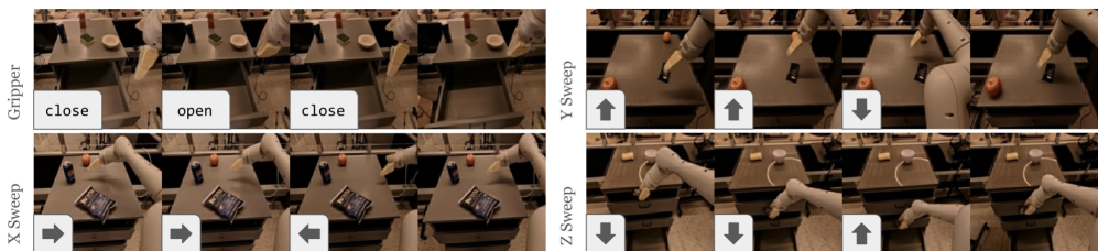
The image depicts a robotic arm performing controlled movements across four distinct operational modes: Gripper, X Sweep, Y Sweep, and Z Sweep. Each mode is represented by a 2x2 grid of frames showing sequential actions, with directional indicators and labels embedded in the visuals.
### Components/Axes
1. **Gripper Section**
- Labels: "close" (left frame), "open" (right frame)
- Positioning: Top-left quadrant, centered above the gripper mechanism.
- Spatial grounding: Text is horizontally aligned with the gripper's jaw position.
2. **X Sweep Section**
- Arrows: Right arrow (→) in the first frame, left arrow (←) in the second frame.
- Positioning: Bottom-left quadrant, aligned with the robotic arm's horizontal axis.
3. **Y Sweep Section**
- Arrows: Upward arrow (↑) in the first frame, downward arrow (↓) in the second frame.
- Positioning: Top-right quadrant, aligned with the vertical axis of the workspace.
4. **Z Sweep Section**
- Arrows: Downward arrow (↓) in the first frame, upward arrow (↑) in the second frame.
- Positioning: Bottom-right quadrant, aligned with the vertical axis of the robotic arm's base.
### Detailed Analysis
- **Gripper**: Explicitly labeled "close" and "open" in the top-left quadrant, indicating the robot's ability to manipulate objects via jaw movement.
- **X Sweep**: Horizontal movement (left/right) is denoted by bidirectional arrows in the bottom-left quadrant.
- **Y Sweep**: Vertical movement (up/down) is shown in the top-right quadrant with opposing arrows.
- **Z Sweep**: Vertical movement (down/up) is depicted in the bottom-right quadrant, suggesting multi-axis coordination.
### Key Observations
- The diagram emphasizes **bidirectional control** for all axes (X, Y, Z) and gripper functionality.
- Arrows are consistently placed in the first frame of each section, with opposing directions in the second frame.
- No numerical data or quantitative metrics are present; the focus is on qualitative movement directions.
### Interpretation
This diagram illustrates the **operational range and control logic** of a robotic arm in a 3D workspace. The labeled movements (X, Y, Z sweeps) and gripper actions suggest a system designed for precise object manipulation, likely for tasks like assembly, sorting, or material handling. The absence of numerical data implies the diagram prioritizes **functional demonstration** over quantitative performance metrics. The bidirectional arrows indicate the robot's ability to reverse motion, critical for dynamic task execution.