## Directed Acyclic Graph: Causal Diagram
### Overview
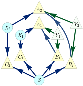
The image presents a directed acyclic graph (DAG) illustrating causal relationships between several variables. The graph consists of nodes represented by circles and triangles, connected by directed edges (arrows) indicating the direction of influence. The nodes are labeled with letters and numbers, and the edges are colored in blue and green to distinguish different types of relationships.
### Components/Axes
* **Nodes:**
* Circles: X1, X2, Z
* Triangles: A1, A2, B1, B2, C1, C2, Y1, Y2
* **Edges (Arrows):**
* Blue: Represents one type of causal relationship.
* Green: Represents another type of causal relationship.
* **Node Positioning:** The nodes are arranged in a roughly circular layout, with node Z at the bottom center.
### Detailed Analysis
The graph shows the following relationships:
* X1 (light blue circle) -> C1 (yellow triangle) (blue arrow)
* X2 (light blue circle) -> C2 (yellow triangle) (blue arrow)
* C1 (yellow triangle) -> Z (light blue circle) (blue arrow)
* C2 (yellow triangle) -> Z (light blue circle) (blue arrow)
* A1 (yellow triangle) -> B1 (yellow triangle) (blue arrow)
* A1 (yellow triangle) -> A2 (yellow triangle) (blue arrow)
* A2 (yellow triangle) -> B2 (yellow triangle) (blue arrow)
* A2 (yellow triangle) -> Y2 (light green triangle) (green arrow)
* A2 (yellow triangle) -> B1 (yellow triangle) (green arrow)
* B1 (yellow triangle) -> Z (light blue circle) (blue arrow)
* B1 (yellow triangle) -> Y1 (light green triangle) (green arrow)
* B2 (yellow triangle) -> Z (light blue circle) (blue arrow)
* Y1 (light green triangle) -> B2 (yellow triangle) (green arrow)
* Y2 (light green triangle) -> B2 (yellow triangle) (green arrow)
* X1 (light blue circle) -> A1 (yellow triangle) (blue arrow)
* X2 (light blue circle) -> A2 (yellow triangle) (blue arrow)
### Key Observations
* Node Z is a sink node, receiving influences from multiple other nodes (C1, C2, B1, B2).
* Nodes X1 and X2 are source nodes, initiating causal chains.
* Nodes A1 and A2 act as central hubs, influencing multiple other nodes.
* The graph contains both blue and green arrows, indicating different types of causal relationships.
* The graph is acyclic, meaning there are no feedback loops.
### Interpretation
The DAG represents a causal model where variables X1 and X2 influence variables C1, C2, A1, and A2. These variables, in turn, influence Z, B1, B2, Y1, and Y2. The different colors of the arrows (blue and green) suggest that the causal relationships may have different strengths or types. The absence of cycles indicates that the causal relationships are unidirectional, with no feedback loops. The model could be used to understand how changes in X1 and X2 might propagate through the system and affect the value of Z, or to identify potential interventions that could influence Z. The model could represent a variety of systems, such as a biological pathway, a social network, or an economic system.