\n
## Diagram: Neuromorphic Computing Architectures & Switching Mechanisms
### Overview
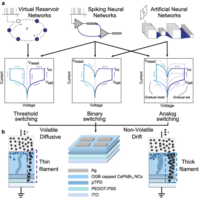
The image presents a comparison of three types of neural networks (Virtual Reservoir Networks, Spiking Neural Networks, and Artificial Neural Networks) and their corresponding switching mechanisms. The top row depicts schematic representations of each network type. The bottom row illustrates the associated current-voltage (I-V) characteristics and the physical mechanisms underlying the switching behavior. The image is divided into two main sections, labeled 'a' and 'b'. Section 'a' focuses on the network architectures and their I-V curves, while section 'b' details the physical structures and switching mechanisms.
### Components/Axes
**Section a:**
* **Network Types (Top Row):** Virtual Reservoir Networks, Spiking Neural Networks, Artificial Neural Networks.
* **I-V Curves (Bottom Row):** Each curve has a Voltage axis (horizontal) and a Current axis (vertical).
* **I-V Curve Labels:** V<sub>reset</sub>, I<sub>cc</sub>, V<sub>set</sub>, "Gradual reset", "Gradual set".
* **Switching Types (Below I-V Curves):** Threshold switching, Binary switching, Analog switching.
* **Switching Properties (Above I-V Curves):** Volatile Diffusive, Non-Volatile Drift.
**Section b:**
* **Physical Structures:** Depictions of thin filament, layered structures, and thick filament configurations.
* **Material Legend:** Ag, OGB capped CsPbBr<sub>3</sub> NCs, pTPD, PEDOT:PSS, ITO.
* **Electrical Connections:** Ground symbol (inverted triangle).
* **Voltage/Current Arrows:** Indicate the direction of current flow.
### Detailed Analysis or Content Details
**Section a: Network Architectures & Switching**
* **Virtual Reservoir Networks:** The schematic shows a network of interconnected nodes with a time constant denoted by τ. The I-V curve exhibits a threshold switching behavior with a clear V<sub>set</sub> and V<sub>reset</sub>. The current rises sharply after V<sub>set</sub> is reached.
* **Spiking Neural Networks:** The schematic depicts a network with a funnel-like input converging onto a neuron. The I-V curve shows binary switching, with a distinct on/off state. V<sub>reset</sub> and V<sub>set</sub> are indicated.
* **Artificial Neural Networks:** The schematic shows a layered structure of interconnected nodes. The I-V curve demonstrates analog switching, with a gradual set and reset behavior. The current changes smoothly with voltage.
**Section b: Physical Structures & Switching Mechanisms**
* **Volatile Diffusive Switching (Left):** A schematic shows a thin filament formed by conductive nanoparticles within an insulating matrix. The filament is connected to a voltage source and ground. The legend indicates the materials: Ag, OGB capped CsPbBr<sub>3</sub> NCs, pTPD, PEDOT:PSS, ITO.
* **Non-Volatile Drift (Right):** A schematic shows a thick filament formed by conductive nanoparticles within an insulating matrix. The filament is connected to a voltage source and ground. The legend indicates the materials: Ag, OGB capped CsPbBr<sub>3</sub> NCs, pTPD, PEDOT:PSS, ITO.
* **Layered Structure (Center):** A schematic shows a layered structure with Ag, OGB capped CsPbBr<sub>3</sub> NCs, pTPD, PEDOT:PSS, and ITO layers.
### Key Observations
* The three network types are linked to distinct switching mechanisms. Virtual Reservoir Networks utilize threshold switching, Spiking Neural Networks employ binary switching, and Artificial Neural Networks leverage analog switching.
* The volatile diffusive switching mechanism involves a thin filament, while the non-volatile drift mechanism utilizes a thick filament.
* The material stack in section 'b' is consistent across all three structures, suggesting a common material platform for implementing these switching mechanisms.
* The I-V curves are qualitatively different, reflecting the different switching behaviors.
### Interpretation
This diagram illustrates the relationship between different neuromorphic computing architectures and the underlying physical mechanisms that enable their functionality. The choice of switching mechanism (threshold, binary, or analog) directly impacts the computational capabilities of the corresponding neural network. The use of metal-organic halide perovskite (CsPbBr<sub>3</sub> NCs) suggests a focus on emerging materials for neuromorphic applications. The distinction between volatile and non-volatile switching highlights the trade-offs between memory retention and energy efficiency. The diagram suggests a pathway for designing and implementing neuromorphic systems by carefully selecting the appropriate network architecture and switching mechanism based on the desired application requirements. The layered structure in the center of section 'b' likely represents a device used to demonstrate the switching mechanisms on either side. The consistent material stack suggests a common fabrication process for all three devices. The diagram is a conceptual overview and does not provide quantitative data on device performance.