## Diagram: Network Graph with Numbered Nodes
### Overview
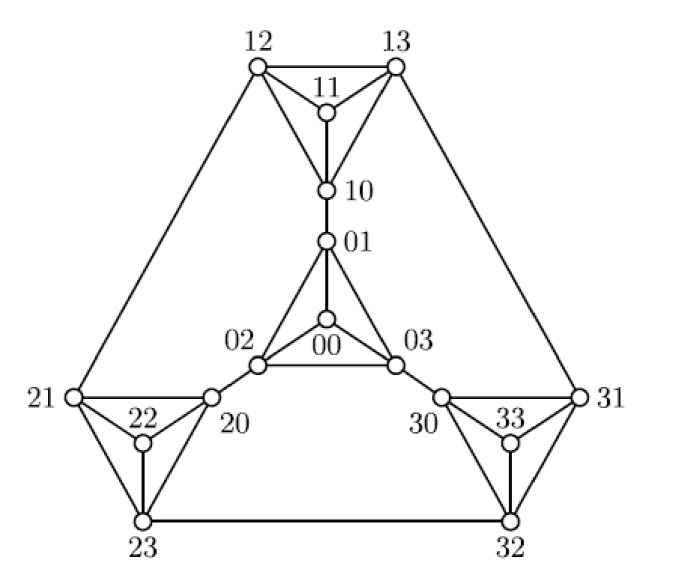
The image displays a directed or undirected graph diagram consisting of 16 circular nodes, each labeled with a unique two-digit number. The nodes are interconnected by straight lines (edges), forming a complex, symmetrical network structure. The layout is hierarchical and geometric, with a central vertical spine and two lateral clusters.
### Components/Axes
* **Nodes:** 16 white circles, each containing a two-digit numerical label.
* **Edges:** Straight black lines connecting the nodes.
* **Labels:** All text consists of the two-digit numbers within or adjacent to the nodes.
* **Spatial Layout:** The graph is arranged with a clear vertical axis of symmetry. It features a central column, a top triangular formation, and two mirrored triangular clusters on the lower left and right.
### Detailed Analysis
**Node Inventory and Connections:**
The nodes can be grouped by their numerical prefix, suggesting a categorical or hierarchical organization.
* **Central Spine (0x & 1x series):**
* `00`: The bottom-most central node. Connected to `01`, `02`, `03`.
* `01`: Directly above `00`. Connected to `00`, `10`, `02`, `03`.
* `10`: Above `01`. Connected to `01`, `11`, `12`, `13`.
* `11`: Above `10`. Connected to `10`, `12`, `13`.
* `12` & `13`: The topmost nodes, forming a horizontal pair. Connected to each other, to `11`, to `10`, and to the lateral clusters (`12` to `21`; `13` to `31`).
* **Left Cluster (2x series):**
* `20`: Inner node of the left cluster. Connected to `02`, `21`, `22`, `23`.
* `21`: Outer-left node. Connected to `20`, `22`, `23`, and the top node `12`.
* `22`: Central node within the left cluster triangle. Connected to `20`, `21`, `23`.
* `23`: Bottom node of the left cluster. Connected to `20`, `21`, `22`, and the right cluster node `32`.
* **Right Cluster (3x series):**
* `30`: Inner node of the right cluster. Connected to `03`, `31`, `32`, `33`.
* `31`: Outer-right node. Connected to `30`, `32`, `33`, and the top node `13`.
* `32`: Bottom node of the right cluster. Connected to `30`, `31`, `33`, and the left cluster node `23`.
* `33`: Central node within the right cluster triangle. Connected to `30`, `31`, `32`.
* **Connecting Nodes:**
* `02`: Bridges the central spine (`00`, `01`) to the left cluster (`20`).
* `03`: Bridges the central spine (`00`, `01`) to the right cluster (`30`).
**Structural Flow:**
The graph exhibits a clear top-down and center-outward flow. The central spine (`00` to `11`) acts as a primary axis. The top nodes (`12`, `13`) connect down to the lateral clusters. The two lateral clusters (`2x` and `3x`) are themselves tightly interconnected internally and are linked to each other at their bases (`23`-`32` edge).
### Key Observations
1. **Symmetry:** The graph is almost perfectly symmetrical about the vertical axis running through nodes `00`, `01`, `10`, `11`.
2. **Hierarchical Grouping:** The first digit of the node labels (`0`, `1`, `2`, `3`) strongly correlates with spatial grouping: `0x`/`1x` are central/vertical, `2x` is left, `3x` is right.
3. **High Connectivity:** Most nodes have a degree (number of connections) of 3 or 4, indicating a robustly connected network. Nodes `01`, `10`, `20`, `21`, `30`, `31` appear to be key hubs.
4. **Triangular Motifs:** The structure is built from interconnected triangles (e.g., `11`-`12`-`13`, `20`-`21`-`22`, `30`-`31`-`33`), which are stable geometric forms.
### Interpretation
This diagram likely represents a **network topology, a system architecture, or a mathematical graph model**. The numbered nodes could symbolize servers, processors, data centers, logical units, or abstract states. The edges represent communication links, dependencies, or relationships.
The structure suggests a **distributed or federated system**. The central spine (`0x`, `1x`) could be a core control or routing layer. The lateral clusters (`2x`, `3x`) might represent separate regional or functional subsystems that are internally cohesive but also connected to the core and to each other (via the `23`-`32` link), enabling redundancy and cross-communication. The top-level connection between `12` and `13` and their links down to the clusters (`21`, `31`) provide an alternative, high-level pathway, possibly for load balancing or failover.
The numerical labeling scheme is systematic, implying an addressable system where the prefix denotes a zone or tier and the suffix denotes an individual unit within that zone. The overall design prioritizes **interconnectivity, symmetry, and hierarchical organization**, which are common principles in reliable network design, parallel computing architectures, or organizational models.