TECHNICAL ASSET FINGERPRINT
89cf08ca5d1a064869321e1e
Click to view fullscreen
Press ESC or click to close
FOUND IN PAPERS
EXPERT: healer-alpha-free VERSION 1
RUNTIME: free/openrouter/healer-alpha
INTEL_VERIFIED
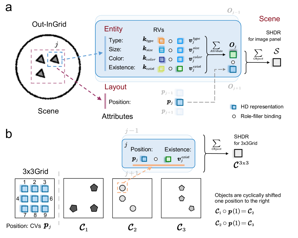
## Diagram: Hierarchical Scene Representation and Cyclic Object Shift
### Overview
The image is a technical diagram split into two primary panels, labeled **a** and **b**. It illustrates a conceptual model for representing scenes composed of objects with attributes and their spatial transformations. Panel **a** details the hierarchical decomposition of a scene into entities with attributes and a layout. Panel **b** demonstrates a specific application of this model to a 3x3 grid, showing how objects undergo a cyclic positional shift.
### Components/Axes
The diagram is not a chart with axes but a conceptual flow diagram. Its components are:
**Panel a:**
* **Left (Scene):** A circular boundary labeled "Scene" containing an "Out-InGrid" region. Inside, three triangular objects are shown. One object (labeled *j*) is highlighted with a blue dashed box, and a larger pink dashed box encloses all three.
* **Center (Entity & Layout):** A blue box labeled "Entity" lists four attributes: **Type**, **Size**, **Color**, and **Existence**. Each attribute is associated with a pair of symbols: a key (*k_type*, *k_size*, *k_color*, *k_exist*) and a value (*v_j^type*, *v_j^size*, *v_j^color*, *v_j^exist*). Small colored squares (orange, blue, purple, green) and circles represent these components. A legend defines the blue square as "HD representation" and the circle as "Role-filler binding".
* **Center-Right (Aggregation):** Arrows show the aggregation process. The attribute values for object *j* are summed (Σ_Atribute) to form a green square representing object *O_j*. This object is then summed with others (Σ_Object) to form the scene representation *S*.
* **Bottom (Layout):** A pink box labeled "Layout" shows "Position" with the symbol *p_j* (a blue square), connected to the object *O_j*. Faded labels *p_{j-1}* and *p_{j+1}* indicate neighboring positions.
* **Right (Scene Output):** The final aggregated scene representation is labeled "SHDR for image panel" and denoted by the symbol *S*.
**Panel b:**
* **Left (3x3Grid):** A 3x3 grid with cells numbered 1 through 9. The cells are labeled "Position: CVs **p_j**".
* **Center (Configurations):** Three square panels labeled **C₁**, **C₂**, and **C₃**. Each contains a different arrangement of geometric shapes (pentagons, circles).
* **Center-Top (Entity Detail):** A simplified entity box for object *j* in the grid, showing only **Position** (*p_j*) and **Existence** (*v_j^exist*). An orange arrow points from the position in grid **C₁** to the position in grid **C₂**.
* **Right (Aggregation & Transformation):** The entity information is summed (Σ_Object) to create "SHDR for 3x3Grid", denoted *C^{3x3}*. Below, text states: "Objects are cyclically shifted one position to the right". Two equations are provided: *C₁ ∘ p(1) = C₂* and *C₂ ∘ p(1) = C₃*.
### Detailed Analysis
**Panel a - Hierarchical Scene Decomposition:**
1. **Entity Representation:** An object *j* in a scene is defined by a set of attributes. Each attribute (e.g., Color) has a key (*k_color*) and a value (*v_j^color*). The diagram uses color-coding: orange for Type, blue for Size, purple for Color, green for Existence.
2. **Binding and Aggregation:** The key and value for each attribute are bound (indicated by the circle "Role-filler binding"). The values (*v_j^type, v_j^size, v_j^color, v_j^exist*) are aggregated (summed) to form a unified representation of the object, *O_j* (green square).
3. **Scene Construction:** All object representations (*O_{j-1}, O_j, O_{j+1}*) are aggregated to form the complete scene representation, *S*.
4. **Layout Integration:** The object's position (*p_j*) is part of the "Layout" and is linked to the object representation *O_j*.
**Panel b - Application to a 3x3 Grid:**
1. **Grid Structure:** The environment is a discrete 3x3 grid with 9 positions, each represented by a control variable (CV) *p_j*.
2. **Cyclic Shift Operation:** The core process shown is a cyclic shift of objects to the right.
* **C₁:** Contains three pentagons at positions (approx.) 4, 6, and 8.
* **C₂:** Contains three circles at positions (approx.) 1, 4, and 7. The text and arrow indicate the object from position 1 in C₁ has moved to position 2 in C₂ (though the visual shows a circle at position 1 in C₂, suggesting the shift is of the *pattern* or *state*, not necessarily the same physical object).
* **C₃:** Contains three pentagons at positions (approx.) 2, 5, and 9.
3. **Mathematical Notation:** The transformation is formalized. *p(1)* likely represents a permutation function that shifts positions by one step to the right. The operator "∘" denotes the application of this permutation to the configuration, so *C₁ ∘ p(1)* means applying the shift to configuration C₁ to produce C₂.
### Key Observations
1. **Abstraction Level:** The diagram operates at a high level of abstraction, using generic symbols (*k, v, p, O, S, C*) to describe a general framework for scene representation and manipulation.
2. **Color Consistency:** Colors are used consistently to track concepts: blue for "HD representation" (keys and positions), green for "Existence" values and aggregated objects.
3. **Two-Level Model:** Panel **a** shows a general, continuous-like scene model. Panel **b** applies a simplified version of it (focusing only on Position and Existence) to a discrete, structured grid environment.
4. **Transformation Logic:** The cyclic shift in panel **b** is demonstrated visually with changing shapes (pentagons to circles to pentagons) and positions, and formalized mathematically. The shapes may represent different object types or states.
### Interpretation
This diagram presents a **structured, compositional approach to visual scene understanding and reasoning**, likely for an AI or computational model.
* **What it suggests:** The model decomposes a scene into a set of objects, each defined by a bundle of attributes (type, size, color, existence) and a spatial location. This is a "role-filler" or "frame-based" representation. The scene is the sum of its objects. This allows for modular manipulation—changing an attribute of one object or moving an object (changing its *p_j*) updates the scene representation predictably.
* **How elements relate:** The flow is bottom-up: attribute keys and values bind to form object representations, which sum to form the scene. The layout (position) is a special attribute linked to the object. Panel **b** shows how this representation can be used to define and execute transformations (like a cyclic shift) on the scene state by operating on the object positions.
* **Notable patterns/anomalies:** The shift from pentagons to circles in panel **b** is interesting. It could imply that the "Existence" value (*v_j^exist*) or the "Type" attribute is being toggled or cycled as part of the transformation, not just the position. The mathematical notation (*C ∘ p(1)*) suggests the framework is designed to support formal, algebraic operations on scene configurations, which is powerful for planning and prediction tasks. The diagram essentially bridges a perceptual representation (the scene image) with a symbolic, manipulable structure (the entity-attribute-layout model).
DECODING INTELLIGENCE...