## Diagram: Conceptual Data/Feature Similarity Flow
### Overview
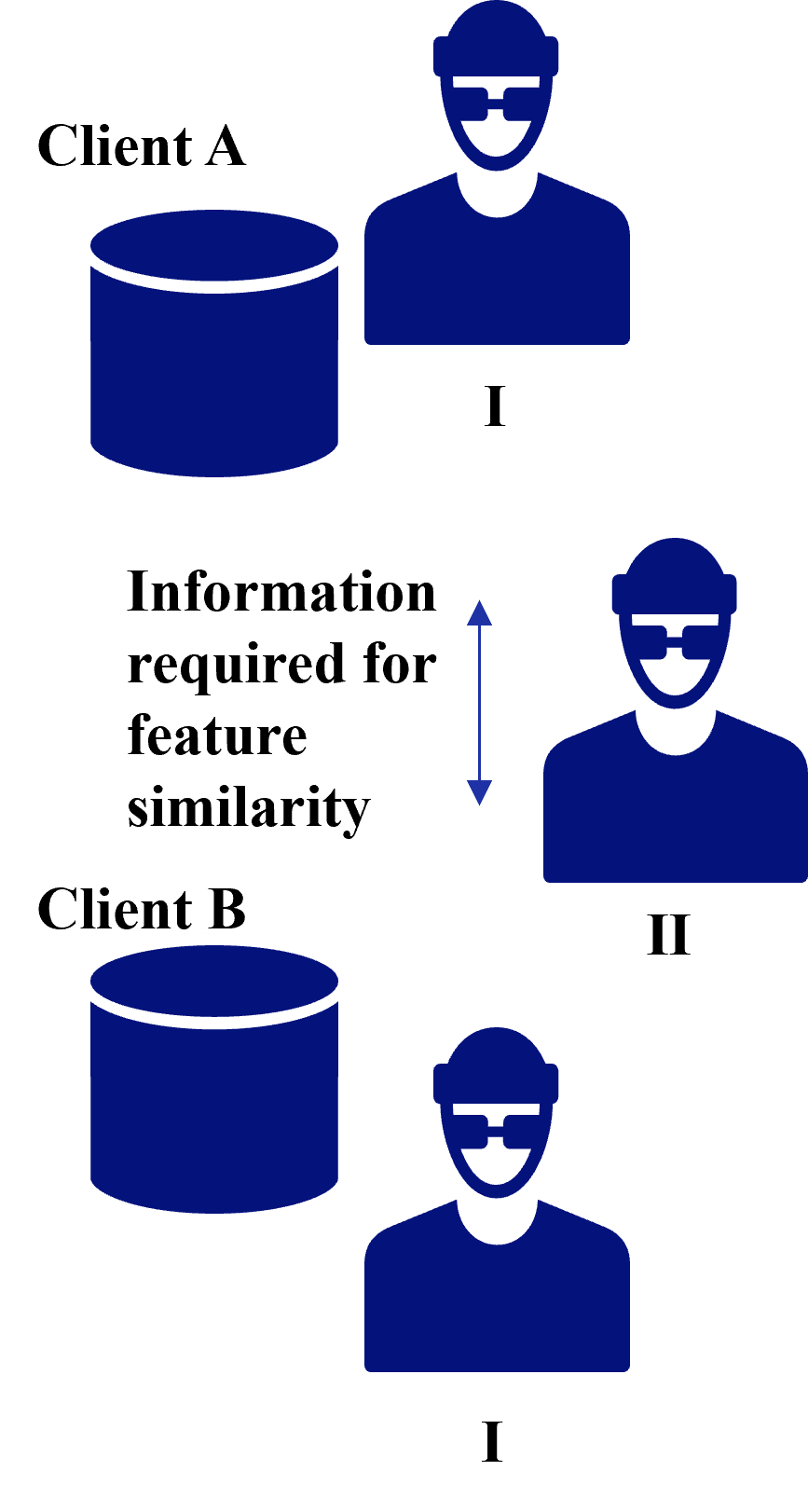
This image is a conceptual diagram illustrating a data relationship or workflow involving two distinct clients (Client A and Client B) and two types of entities (labeled I and II). The diagram highlights a requirement for information exchange or comparison to establish "feature similarity" between these entities.
### Components/Axes
* **Entities:**
* **Client A (Top-Left):** Comprised of a database cylinder icon and a person icon labeled "I".
* **Client B (Bottom-Left):** Comprised of a database cylinder icon and a person icon labeled "I".
* **Person II (Middle-Right):** A standalone person icon positioned between the two client groups.
* **Textual Elements:**
* "Client A" (Top-left)
* "Client B" (Bottom-left)
* "Information required for feature similarity" (Center-left)
* "I" (Located below the person icons at the top and bottom)
* "II" (Located below the person icon in the middle)
* **Visual Indicators:**
* **Vertical Double-Headed Arrow:** Positioned to the right of the text "Information required for feature similarity," indicating a bidirectional relationship or a flow of information.
* **Cylinder Icons:** Representing data storage or databases for Client A and Client B.
* **Person Icons:** Representing users, agents, or data owners.
### Detailed Analysis
* **Top Region:** Contains the label "Client A" above a database cylinder. To the right of the database is a person icon labeled "I".
* **Middle Region:** Contains the text "Information required for feature similarity" aligned vertically. A double-headed arrow is placed to the right of this text, suggesting a connection between the top and bottom sections. To the right of this arrow is a person icon labeled "II".
* **Bottom Region:** Contains the label "Client B" above a database cylinder. To the right of the database is a person icon labeled "I".
* **Consistency:** The person icons labeled "I" are identical in design. The person icon labeled "II" is also identical in design to the "I" icons, suggesting they represent the same type of entity (e.g., a user or agent) but in different roles or contexts.
### Key Observations
* **Symmetry:** The diagram is vertically symmetrical regarding the "Client" and "Person I" components.
* **Centrality:** "Person II" acts as a central or intermediary figure, distinct from the local "Person I" entities associated with the databases.
* **Functional Requirement:** The text "Information required for feature similarity" is the central functional description, implying that the interaction between the entities is driven by the need to compare features without necessarily exposing raw data.
### Interpretation
This diagram likely represents a **Federated Learning** or **Privacy-Preserving Machine Learning** architecture.
* **The Data Silos:** "Client A" and "Client B" represent local data sources (databases) that cannot be merged directly.
* **The Local Agents:** "Person I" represents the local data owner or local compute agent at each client site.
* **The Aggregator/Server:** "Person II" represents a central server or an orchestrator.
* **The Process:** The text "Information required for feature similarity" suggests that the system needs to compute a similarity metric (e.g., cosine similarity, correlation) between the features of Client A and Client B. Because the data is siloed, the system must exchange specific, likely anonymized or aggregated, information with the central entity ("Person II") to perform this calculation without violating data privacy. The double-headed arrow indicates the iterative nature of this communication (e.g., sending gradients or feature embeddings and receiving updates).