\n
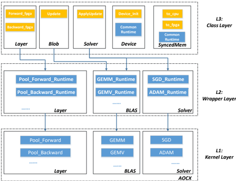
## Diagram: Layered System Architecture
### Overview
The image depicts a layered system architecture, likely related to deep learning or numerical computation. It consists of three layers (L1, L2, L3) with various components interconnected by arrows indicating data or control flow. The diagram illustrates how high-level operations in the Class Layer (L3) are decomposed into lower-level operations in the Kernel Layer (L1) through the Wrapper Layer (L2).
### Components/Axes
The diagram is structured into three distinct layers, labeled L1 (Kernel Layer), L2 (Wrapper Layer), and L3 (Class Layer), positioned vertically from bottom to top. Each layer contains several rectangular blocks representing components. Arrows connect these blocks, showing dependencies and data flow.
**L3 (Class Layer):**
* Forward\_fgga
* Backward\_fgga
* Update
* ApplyUpdate
* Device\_Init
* to\_cpu
* to\_joga
* Layer
* Blob
* Solver
* Common Runtime
* Device
* Common Runtime SyncedMem
**L2 (Wrapper Layer):**
* Pool\_Forward\_Runtime
* Pool\_Backward\_Runtime
* GEMM\_Runtime
* GEMV\_Runtime
* SGD\_Runtime
* ADAM\_Runtime
* Layer
* BLAS
* Solver
**L1 (Kernel Layer):**
* Pool\_Forward
* Pool\_Backward
* GEMM
* GEMV
* SGD
* ADAM
* Layer
* BLAS
* Solver
* AOCX
### Detailed Analysis or Content Details
The diagram shows a hierarchical decomposition of operations.
* **L3 to L2:** `Forward_fgga` and `Backward_fgga` connect to `Pool_Forward_Runtime` and `Pool_Backward_Runtime` respectively. `Update` and `ApplyUpdate` connect to `SGD_Runtime` and `ADAM_Runtime`. `Device_Init` connects to `GEMM_Runtime` and `GEMV_Runtime`. `Layer` connects to `Layer` in L2. `Blob` connects to `BLAS`. `Solver` connects to `Solver` in L2. `Common Runtime` connects to `BLAS`. `Device` connects to `GEMM_Runtime` and `GEMV_Runtime`. `Common Runtime SyncedMem` connects to `SGD_Runtime` and `ADAM_Runtime`.
* **L2 to L1:** `Pool_Forward_Runtime` and `Pool_Backward_Runtime` connect to `Pool_Forward` and `Pool_Backward`. `GEMM_Runtime` and `GEMV_Runtime` connect to `GEMM` and `GEMV`. `SGD_Runtime` and `ADAM_Runtime` connect to `SGD` and `ADAM`. `Layer` connects to `Layer` in L1. `BLAS` connects to `BLAS` in L1. `Solver` connects to `Solver` and `AOCX` in L1.
The dotted lines between components within each layer suggest internal connections or data flow within that layer.
### Key Observations
* The diagram emphasizes a layered approach to software design, where higher-level functionalities are built upon lower-level primitives.
* The presence of both `SGD` and `ADAM` suggests support for multiple optimization algorithms.
* The inclusion of `BLAS` indicates the use of optimized linear algebra routines.
* The `fgga` suffix in `Forward_fgga` and `Backward_fgga` might refer to a specific framework or implementation detail.
* The `AOCX` component in L1 is unique and might represent a specific hardware accelerator or compilation target.
### Interpretation
This diagram likely represents the architecture of a deep learning framework or a numerical computation library. The layered structure allows for abstraction and portability. The Class Layer (L3) provides a high-level interface for users, while the Kernel Layer (L1) contains the core computational kernels optimized for specific hardware. The Wrapper Layer (L2) acts as a bridge between the two, providing a consistent interface and handling data transformations.
The connections between layers illustrate the flow of operations. For example, a forward pass through a neural network would start at the `Forward_fgga` component in L3, propagate down to the `Pool_Forward` and `GEMM` components in L1, and then return the results back up the layers.
The presence of `AOCX` suggests that the framework is designed to leverage specific hardware acceleration capabilities. The dotted lines within each layer indicate internal dependencies and data flow, which are crucial for performance optimization. The diagram highlights a modular and extensible design, allowing for easy integration of new components and algorithms.