## Network Diagram: Hierarchical Node Structure
### Overview
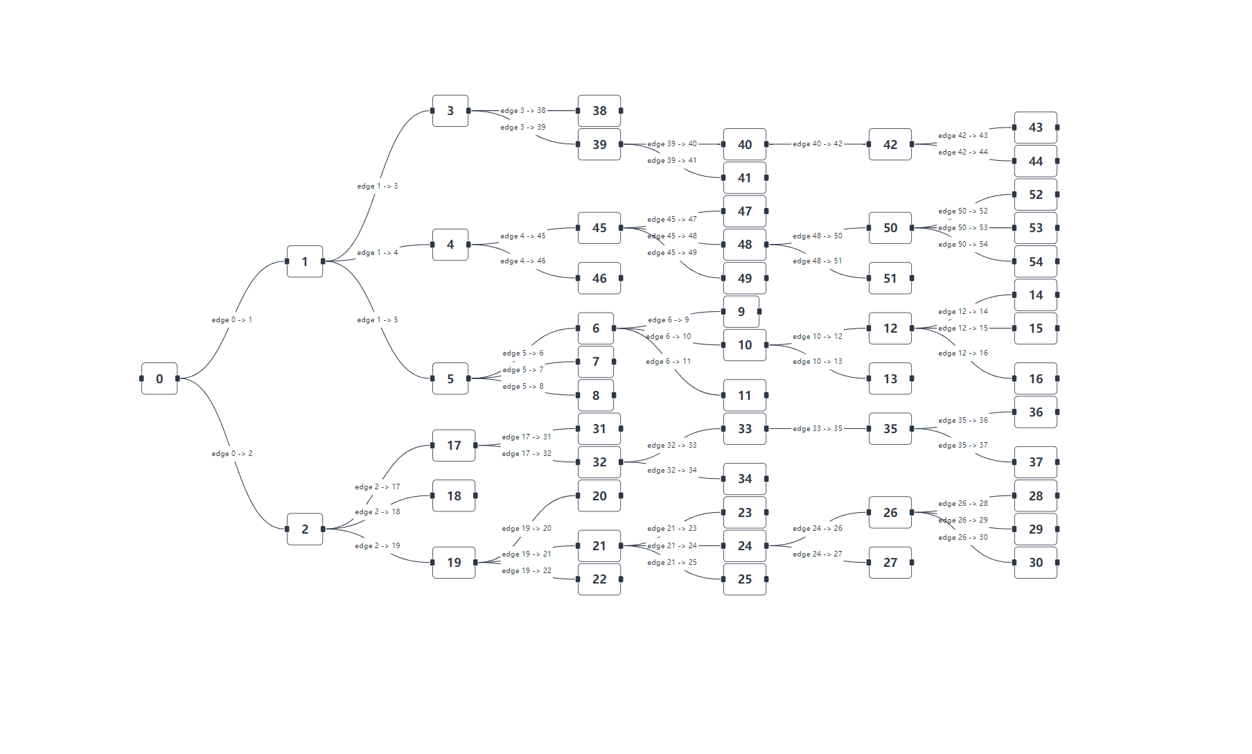
The image depicts a hierarchical network diagram with nodes labeled 0 to 50 connected by directed edges. The structure forms a tree-like hierarchy with multiple branching levels, starting from a root node (0) and expanding through successive layers. Edges are explicitly labeled with source-target node pairs (e.g., "edge 0 -> 1").
### Components/Axes
- **Nodes**: Labeled sequentially from 0 to 50, arranged in hierarchical levels.
- **Edges**: Directed connections between nodes, labeled with source-target pairs (e.g., "edge 0 -> 1", "edge 1 -> 3").
- **Hierarchy Levels**:
- **Level 1**: Root node 0.
- **Level 2**: Nodes 1 and 2 (children of 0).
- **Level 3**: Nodes 3-5 (children of 1) and 17-19 (children of 2).
- **Subsequent Levels**: Nodes branch further (e.g., node 3 connects to 38, 39; node 4 connects to 45, 46; etc.).
- **Leaf Nodes**: Terminal nodes with no outgoing edges (e.g., 43, 44, 50).
### Detailed Analysis
- **Root Node (0)**: Connects to nodes 1 and 2.
- **Branching Pattern**:
- Node 1 → 3, 4, 5.
- Node 2 → 17, 18, 19.
- Nodes 3-50 follow similar branching (e.g., node 3 → 38, 39; node 4 → 45, 46).
- **Edge Labels**: Explicitly denote source-target relationships (e.g., "edge 39 -> 40", "edge 49 -> 50").
- **Terminal Nodes**: Nodes 43-50 have no outgoing edges, marking the end of branches.
### Key Observations
1. **Hierarchical Organization**: The diagram represents a tree structure with a clear root (node 0) and terminal nodes (43-50).
2. **Branching Factor**: Most nodes have 2-3 children (e.g., node 1 has 3 children; node 3 has 2 children).
3. **Edge Labeling**: Edges are uniquely identified by source-target pairs, ensuring unambiguous connectivity.
4. **Depth**: The tree extends to at least 6 levels (e.g., node 0 → 1 → 3 → 38 → 42 → 43).
### Interpretation
The diagram illustrates a **directed acyclic graph (DAG)** structured as a tree, likely representing:
- A **decision tree** (nodes as decisions, edges as outcomes).
- A **network topology** (nodes as devices, edges as connections).
- A **data flow hierarchy** (nodes as processing stages, edges as data paths).
The explicit edge labeling suggests a focus on traceability or dependency mapping. The absence of weights or probabilities implies the diagram prioritizes structure over quantitative analysis. The terminal nodes (43-50) may represent final states or endpoints in the system.