## Mathematical Diagram: Model Transformation Flowchart
### Overview
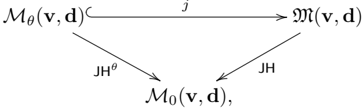
The image displays a mathematical flowchart or diagram illustrating relationships between three distinct mathematical entities, connected by directional arrows with operational labels. The diagram uses calligraphic and standard mathematical notation, suggesting a context in optimization, machine learning, or functional analysis.
### Components/Axes
The diagram consists of three primary nodes and three connecting arrows, arranged in a triangular layout.
**Nodes (Mathematical Expressions):**
1. **Top-Left Node:** `M_θ(v, d)^C`
* `M`: Calligraphic uppercase M.
* Subscript: `θ` (Greek letter theta).
* Parenthetical arguments: `(v, d)`.
* Superscript: `C`.
2. **Top-Right Node:** `M(v, d)`
* `M`: Calligraphic uppercase M (same style as top-left).
* Parenthetical arguments: `(v, d)`.
3. **Bottom-Center Node:** `M_0(v, d),`
* `M`: Standard uppercase M (non-calligraphic).
* Subscript: `0` (zero).
* Parenthetical arguments: `(v, d)`.
* Followed by a comma.
**Arrows and Labels:**
1. **Horizontal Arrow (Top):** Connects the top-left node to the top-right node.
* **Direction:** Left to right.
* **Label:** `J` (positioned above the arrow's midpoint).
2. **Diagonal Arrow (Left):** Connects the top-left node to the bottom-center node.
* **Direction:** Top-left to bottom-center.
* **Label:** `JH^θ` (positioned to the left of the arrow's midpoint).
3. **Diagonal Arrow (Right):** Connects the top-right node to the bottom-center node.
* **Direction:** Top-right to bottom-center.
* **Label:** `JH` (positioned to the right of the arrow's midpoint).
### Detailed Analysis
* **Spatial Layout:** The diagram forms an inverted "V" or triangle. The two `M`-based entities are positioned at the top (left and right), both feeding into a single `M_0` entity at the bottom center.
* **Notation Details:**
* The use of calligraphic `M` for the top nodes versus standard `M` for the bottom node suggests a distinction in the type or state of the model/function.
* The subscript `θ` in the top-left node and its corresponding arrow label `JH^θ` indicates a parameterization or specific instance related to `θ`.
* The superscript `C` on the top-left node is unique to that entity.
* The arguments `(v, d)` are consistent across all three nodes, implying they operate on the same input variables.
* **Flow Interpretation:** The arrows define a clear directional flow:
1. A transformation `J` maps `M_θ(v, d)^C` to `M(v, d)`.
2. A transformation `JH^θ` maps `M_θ(v, d)^C` directly to `M_0(v, d)`.
3. A transformation `JH` maps `M(v, d)` to `M_0(v, d)`.
### Key Observations
1. **Convergent Structure:** Both top-level entities converge to produce the same bottom-level entity, `M_0(v, d)`.
2. **Parameter Dependency:** The path from the top-left node involves the parameter `θ` (`JH^θ`), while the path from the top-right node does not (`JH`). This suggests `M_θ(v, d)^C` is a parameterized variant, and `M(v, d)` may be a base or alternative form.
3. **Symbolic Consistency:** The repeated use of `J` and `H` in the arrow labels implies these represent fundamental operations (e.g., Jacobian, Hessian, or other linear/nonlinear operators) applied in sequence or combination.
### Interpretation
This diagram likely represents a **factorization, decomposition, or equivalence relationship** between different formulations of a model or function `M` that depends on variables `v` and `d`.
* **What it suggests:** The structure implies that the entity `M_0(v, d)` can be derived via two distinct pathways from two related but different starting points (`M_θ(v, d)^C` and `M(v, d)`). This is common in mathematical proofs, optimization derivations (e.g., showing different objective functions lead to the same solution), or in defining model relationships (e.g., a constrained model `M_θ^C` and an unconstrained model `M` both relating to a base model `M_0`).
* **Relationships:** The diagram establishes that `M_θ(v, d)^C` is linked to `M(v, d)` via operation `J`. Furthermore, both are linked to `M_0(v, d)` via operations that include `H` (with `H` possibly being modified by `θ` in one case). This could illustrate a chain rule application, a change of variables, or the relationship between a model, its constraint, and a Lagrangian or related function.
* **Notable Anomalies:** The comma after `M_0(v, d),` is unusual in a standalone diagram and may indicate this node is part of a larger equation or list that was cropped. The lack of context for symbols `J`, `H`, `θ`, `v`, `d`, and `C` limits a definitive interpretation, but the structure is characteristic of formal mathematical or theoretical computer science literature.
**Language Declaration:** All text in the image is mathematical notation, which is language-agnostic. The symbols are transcribed directly above.