## Diagram: Architecture of a Transformer Layer and its relation to a Decoder-only LLM
### Overview
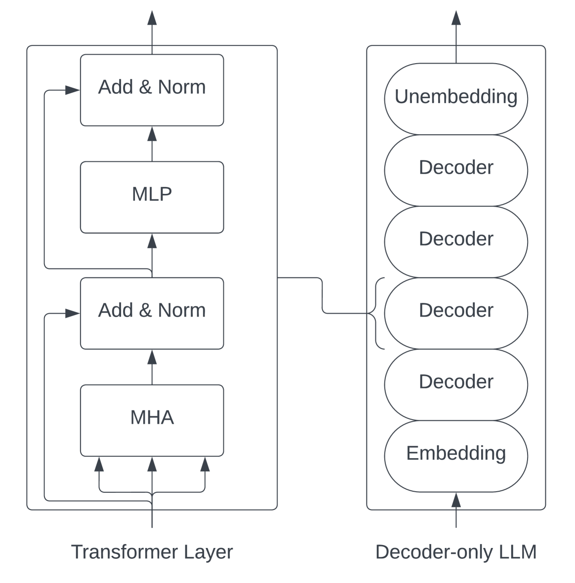
The image presents a two-part architectural diagram. On the left, it details the internal structure of a single "Transformer Layer." On the right, it provides a high-level overview of a "Decoder-only LLM" (Large Language Model) stack. A connecting line indicates that the Transformer Layer on the left is the fundamental building block that constitutes the "Decoder" blocks shown on the right.
### Components/Axes
**Left Box: Transformer Layer**
* **Structure:** A vertical stack of four processing blocks enclosed in a rectangular frame.
* **Bottom Block:** "MHA" (Multi-Head Attention).
* **Second Block (from bottom):** "Add & Norm".
* **Third Block (from bottom):** "MLP" (Multi-Layer Perceptron).
* **Top Block:** "Add & Norm".
* **Flow:** Data enters at the bottom, flows upward through the blocks, and exits at the top.
* **Residual Connections:** Two distinct lines loop back from the output of the MHA and MLP stages to the inputs of the subsequent "Add & Norm" blocks, representing residual (skip) connections.
**Right Box: Decoder-only LLM**
* **Structure:** A vertical stack of six oval-shaped blocks enclosed in a rectangular frame.
* **Bottom Block:** "Embedding".
* **Middle Blocks (4 total):** "Decoder".
* **Top Block:** "Unembedding".
* **Flow:** Data enters at the bottom, passes through the Embedding layer, the stack of four Decoder blocks, and finally the Unembedding layer, exiting at the top.
**Connecting Element**
* A line originates from the top of the "Transformer Layer" box and points to a bracket that encompasses all four "Decoder" blocks in the "Decoder-only LLM" box.
### Detailed Analysis
* **Transformer Layer (Left):**
* The architecture follows a standard Transformer block design.
* The input is processed by the **MHA** (Multi-Head Attention) mechanism.
* The output of the MHA is fed into the first **Add & Norm** block, which also receives the original input via a residual connection.
* The output of this normalization is then fed into the **MLP** (Multi-Layer Perceptron) block.
* The output of the MLP is fed into the final **Add & Norm** block, which also receives the input from the previous stage via a second residual connection.
* The final output is the result of this sequence.
* **Decoder-only LLM (Right):**
* This represents the macro-architecture of the model.
* **Embedding:** Converts input tokens into vector representations.
* **Decoder Stack:** A sequence of four identical "Decoder" blocks.
* **Unembedding:** Converts the final vector representations back into token probabilities (logits).
### Key Observations
* **Modular Composition:** The diagram explicitly defines the "Decoder" block in the LLM as an abstraction of the "Transformer Layer" detailed on the left.
* **Residual Connections:** The presence of the looping arrows in the Transformer Layer highlights the importance of residual connections, which are essential for training deep neural networks by mitigating the vanishing gradient problem.
* **Sequential Processing:** Both diagrams emphasize a strictly sequential, bottom-to-top flow of information.
### Interpretation
This diagram serves as a bridge between the micro-architecture (the mathematical operations within a single layer) and the macro-architecture (the overall model structure) of modern LLMs.
* **The "Decoder-only" Paradigm:** The right side of the diagram illustrates why these models are called "Decoder-only." They lack an "Encoder" component (which would typically process input sequences separately). Instead, they rely on a stack of Decoders that process the input and generate output autoregressively.
* **The Role of the Transformer Layer:** By linking the Transformer Layer to the Decoder blocks, the diagram clarifies that the "Decoder" is not a single operation, but a complex block containing Attention (MHA) and Feed-Forward (MLP) mechanisms.
* **Scalability:** The representation of the Decoder as a stack of four blocks suggests that the capacity of the LLM can be scaled by simply increasing the number of these Transformer Layers (depth).
* **Peircean Investigative Note:** The diagram is a classic example of "zooming" in technical documentation. It moves from the *system* (the LLM) to the *sub-system* (the Transformer Layer), allowing the viewer to understand that the "Decoder" is a recursive, repeating unit. The residual connections are the most critical "hidden" detail here, as they are the architectural feature that allows these models to be stacked so deeply without losing signal integrity.