## Block Diagram: CPU Instruction Processing Pipeline
### Overview
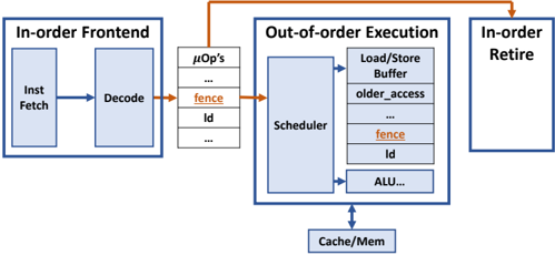
This diagram illustrates a simplified CPU instruction processing pipeline, highlighting the interaction between in-order and out-of-order execution components. It shows three primary stages: In-order Frontend, Out-of-order Execution, and In-order Retire, with explicit data flow paths and synchronization mechanisms.
### Components/Axes
1. **In-order Frontend**
- Inst Fetch (Instruction Fetch)
- Decode
- Arrows indicate sequential flow from Fetch → Decode
2. **Out-of-order Execution**
- Scheduler (central component)
- Load/Store Buffer
- older_access (likely a dependency tracking mechanism)
- fence (synchronization primitive)
- id (instruction identifier)
- ALU (Arithmetic Logic Unit)
- Arrows show parallel execution paths from Scheduler to all components
3. **In-order Retire**
- Single block with no internal components
- Receives input from Out-of-order Execution via orange arrow
4. **Memory Hierarchy**
- Cache/Mem (bottom component)
- Connected to Scheduler via downward arrow
5. **Micro-operations (µOp's)**
- Listed vertically between In-order Frontend and Out-of-order Execution
- Contains: "fence", "id", and ellipses indicating additional operations
### Detailed Analysis
- **Instruction Flow**:
1. Instructions flow left-to-right through In-order Frontend (Fetch → Decode)
2. Decoded instructions enter µOp's list
3. µOp's feed into Out-of-order Execution Scheduler
4. Scheduler distributes work to:
- Load/Store Buffer (memory operations)
- ALU (compute operations)
- fence (synchronization)
- id (instruction tracking)
5. Results flow back to In-order Retire
6. Cache/Mem serves as shared memory resource for all execution units
- **Synchronization**:
- fence instruction appears in both µOp's list and Scheduler outputs
- Indicates critical role in maintaining memory ordering constraints
- orange arrows emphasize synchronization points
### Key Observations
1. **Ordering Constraints**:
- In-order Frontend and Retire maintain sequential processing
- Out-of-order Execution allows parallelism while preserving correctness
2. **Critical Components**:
- Scheduler acts as central dispatcher
- fence instruction appears twice, emphasizing its importance
- Load/Store Buffer handles memory operations separately from ALU
3. **Data Flow**:
- Blue arrows represent normal data/instruction flow
- Orange arrows highlight synchronization points
- Vertical µOp's list acts as intermediary buffer
### Interpretation
This architecture demonstrates modern CPU design principles:
1. **Performance Optimization**:
- Out-of-order execution enables instruction-level parallelism
- Separation of fetch/decode from execution allows pipeline efficiency
2. **Correctness Mechanisms**:
- In-order Retire ensures program-visible ordering
- fence instructions enforce memory operation ordering
- Instruction IDs track dependencies despite out-of-order execution
3. **Memory Hierarchy**:
- Cache/Mem serves as shared resource for all execution units
- Load/Store Buffer likely implements store queue functionality
The diagram reveals a balance between in-order correctness (front-end/retire stages) and out-of-order performance (execution stage), with explicit synchronization points to maintain program semantics. The double appearance of "fence" suggests it's a critical primitive for memory consistency in this architecture.