## Diagram: Vehicle Sensor Fusion and Braking Control System
### Overview
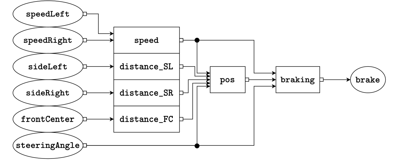
The image displays a technical block diagram illustrating a data flow or control system, likely for an autonomous or advanced driver-assistance vehicle. It maps sensor inputs through processing stages to a final braking actuator output. The diagram uses ovals for input/output nodes and rectangles for processing blocks, connected by directional arrows.
### Components/Axes
**Input Nodes (Ovals, Left Side):**
* `speedLeft`
* `speedRight`
* `sideLeft`
* `sideRight`
* `frontCenter`
* `steeringAngle`
**Processing Blocks (Rectangles, Center):**
* `speed` (receives `speedLeft` and `speedRight`)
* `distance_SL` (receives `sideLeft`)
* `distance_SR` (receives `sideRight`)
* `distance_FC` (receives `frontCenter`)
* `pos` (receives outputs from `speed`, `distance_SL`, `distance_SR`, `distance_FC`, and `steeringAngle`)
* `braking` (receives output from `pos`)
**Output Node (Oval, Right Side):**
* `brake`
### Detailed Analysis / Content Details
**Data Flow and Connections:**
1. **Input Layer:** Six sensor inputs are defined. `speedLeft` and `speedRight` are paired, as are `sideLeft`/`sideRight`. `frontCenter` and `steeringAngle` are singular inputs.
2. **First Processing Stage:** Inputs are routed to dedicated processing blocks:
* `speedLeft` & `speedRight` → `speed` block.
* `sideLeft` → `distance_SL` block.
* `sideRight` → `distance_SR` block.
* `frontCenter` → `distance_FC` block.
3. **Sensor Fusion Stage:** The outputs from all four first-stage blocks (`speed`, `distance_SL`, `distance_SR`, `distance_FC`) are fed into the `pos` block. The `steeringAngle` input also connects directly to the `pos` block, bypassing the first stage.
4. **Decision & Actuation Stage:** The `pos` block outputs to the `braking` block. The `braking` block's output connects to the final `brake` actuator node.
**Spatial Grounding:**
* Inputs are vertically stacked on the far left.
* The first-stage processing blocks are vertically stacked in the center-left.
* The `pos` block is centrally located.
* The `braking` block is to the right of `pos`.
* The final `brake` output is on the far right.
* All connections are indicated by solid black lines with arrowheads showing flow direction from left to right.
### Key Observations
* **Hierarchical Processing:** The system has a clear two-stage processing architecture before the final braking decision.
* **Direct Steering Input:** The `steeringAngle` has a unique, direct connection to the `pos` block, suggesting it is a critical parameter for position/state calculation, not just a distance or speed metric.
* **Symmetry:** Inputs for left/right sides (`speedLeft/Right`, `sideLeft/Right`) are processed symmetrically before fusion.
* **Single Output:** The entire complex sensor array and processing chain culminates in a single actuator command: `brake`.
### Interpretation
This diagram represents a **sensor fusion and control logic pipeline** for a vehicle's automated braking system. The underlying principle is that safe braking decisions (`brake`) depend on a synthesized understanding of the vehicle's state and environment (`pos`).
* **What it demonstrates:** The system fuses dynamic data (wheel speeds), spatial awareness data (side and front distances), and driver intent/vehicle dynamics data (steering angle) to compute a position or state estimate (`pos`). This estimate is then used by a dedicated `braking` controller to determine the appropriate braking action.
* **Relationships:** The flow shows a transformation from raw sensor data → processed metrics (speed, distances) → fused situational awareness (`pos`) → control decision (`braking`) → physical actuation (`brake`). The `pos` block is the critical nexus where all information converges.
* **Notable Implications:** The architecture implies that braking is not triggered by a single sensor (e.g., front distance alone) but by a holistic assessment. The direct link from `steeringAngle` to `pos` is particularly important, as it indicates the system accounts for the vehicle's trajectory and intended path when calculating its state, which is essential for functions like stability control or predictive emergency braking in curves. The absence of numerical values indicates this is a conceptual or architectural diagram, not a performance chart.