## Diagram: Adder with Carry
### Overview
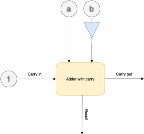
The image is a diagram of an adder with carry, illustrating the inputs and outputs of the adder. The diagram shows the flow of data into and out of the adder, including carry-in, carry-out, and the result.
### Components/Axes
* **Inputs:**
* 'a' - Input 'a' to the adder. Represented by a circle with the letter 'a' inside.
* 'b' - Input 'b' to the adder. Represented by a circle with the letter 'b' inside, connected to a blue triangle pointing downwards.
* 'Carry in' - Carry-in input to the adder. Represented by a circle with the number '1' inside.
* **Process:**
* 'Adder with carry' - The main processing block, represented by a yellow rounded rectangle.
* **Outputs:**
* 'Carry out' - Carry-out output from the adder.
* 'Result' - The result of the addition.
### Detailed Analysis
* The diagram shows three inputs to the "Adder with carry" block: 'a', 'b', and 'Carry in'.
* The 'a' input comes directly from a source labeled 'a'.
* The 'b' input comes from a source labeled 'b', which is connected to a blue triangle pointing downwards.
* The 'Carry in' input comes from a source labeled '1'.
* The "Adder with carry" block has two outputs: 'Carry out' and 'Result'.
* The 'Carry out' output goes to the right.
* The 'Result' output goes downwards.
### Key Observations
* The diagram illustrates the basic components and flow of data in an adder with carry.
* The blue triangle pointing downwards connected to 'b' is likely an inverter.
### Interpretation
The diagram represents a full adder circuit. The 'a' and 'b' inputs are the two numbers being added. The 'Carry in' input is the carry from the previous stage of addition. The 'Adder with carry' block performs the addition and generates two outputs: the 'Result' (sum) and the 'Carry out' (carry to the next stage). The blue triangle pointing downwards connected to 'b' likely represents an inverter, suggesting that the 'b' input might be inverted before being fed into the adder.