## Diagram: Diagram of a Transformation
### Overview
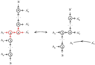
The image shows a diagram illustrating a transformation between two configurations of interconnected nodes and lines. The diagram consists of two main parts, one on the left and one on the right, connected by a double-headed arrow indicating a transformation or equivalence. Each part shows a network of nodes labeled with 'A' and 'B' variants, connected by lines with arrows indicating direction.
### Components/Axes
* **Nodes:** Represented by circles, some containing the symbol 'λ'.
* **Lines:** Represent connections between nodes, with arrows indicating direction.
* **Labels:** 'A1', 'A2', 'An', 'A1*', 'A1'', 'A2'', 'An'', 'B', 'B'' are used to label the nodes.
* **Double-Headed Arrow:** Located in the center, indicating a transformation or equivalence between the left and right configurations.
### Detailed Analysis
**Left Configuration:**
* A node labeled 'B' is at the bottom.
* A series of nodes labeled 'An', 'A2', and 'A1' are connected vertically, moving upwards from 'B'. Each node has an arrow pointing upwards.
* The node labeled 'A1' is highlighted with a red circle.
* From 'A1', two arrows extend horizontally to the right, connecting to a node labeled 'A1*'.
* Above 'A1', there is a series of nodes labeled 'A2'' and 'An'', leading to a node labeled 'B'' at the top.
**Right Configuration:**
* A node labeled 'B' is at the bottom.
* A series of nodes labeled 'An', 'A2' are connected vertically, moving upwards from 'B'. Each node has an arrow pointing upwards.
* At the top of the vertical series, there is a central node.
* From the central node, two arrows extend horizontally to the right and left, connecting to nodes labeled 'A2'' and 'A2'.
* Above the central node, there is a series of nodes labeled 'An'', leading to a node labeled 'B'' at the top.
* A curved arrow connects 'A1' to 'A1*'.
### Key Observations
* The transformation involves rearranging the connections between the nodes.
* The 'A1' node and its connection to 'A1*' are highlighted in the left configuration.
* The right configuration shows a more symmetrical arrangement of nodes.
### Interpretation
The diagram illustrates a transformation or equivalence between two different network configurations. The transformation appears to involve rearranging the connections around the 'A1' node, which is highlighted in the left configuration. The double-headed arrow suggests that the two configurations are equivalent in some sense, possibly representing different ways of representing the same underlying system or process. The use of 'λ' within some nodes might indicate a specific type of operation or function associated with those nodes. The diagram likely represents a step in a larger process or a simplification of a more complex system.