\n
## Diagram: Multi-Head Loss Architecture
### Overview
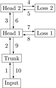
The image depicts a diagram of a multi-head loss architecture, likely used in a machine learning model. It shows a flow of information from an "Input" through a "Trunk", then branching into two "Heads" each connected to a "Loss" component. Numbered arrows indicate the direction of data flow and potentially represent stages or connections within the model.
### Components/Axes
The diagram consists of the following components:
* **Input:** The starting point of the data flow.
* **Trunk:** A central processing unit that receives input and distributes it to the heads.
* **Head 1:** One of the processing heads.
* **Head 2:** The second processing head.
* **Loss 1:** The loss function associated with Head 1.
* **Loss 2:** The loss function associated with Head 2.
* **Arrows (1-10):** Indicate the direction of data flow between components.
There are no axes or scales present in this diagram.
### Detailed Analysis or Content Details
The diagram shows a sequential flow of data, with branching and feedback loops. Here's a breakdown of the connections and their associated numbers:
1. Data flows from "Input" to "Trunk" (labeled '10').
2. Data flows from "Trunk" to "Head 1" (labeled '9').
3. Data flows from "Trunk" to "Head 2" (labeled '6').
4. Data flows from "Head 2" to "Loss 2" (labeled '4').
5. Data flows from "Loss 2" to "Head 2" (labeled '5'). This indicates a feedback loop.
6. Data flows from "Head 1" to "Loss 1" (labeled '7').
7. Data flows from "Loss 1" to "Head 1" (labeled '8'). This indicates a feedback loop.
8. Data flows from "Head 1" to "Trunk" (labeled '2').
9. Data flows from "Head 2" to "Trunk" (labeled '3').
10. Data flows from "Input" to "Trunk" (labeled '1').
### Key Observations
The architecture features two parallel "Heads" processing data from a shared "Trunk". Each head has its own associated "Loss" function, and both heads feed back into the "Trunk". This suggests a multi-task learning or a model with multiple objectives. The feedback loops from the loss functions to the heads suggest a gradient-based optimization process.
### Interpretation
This diagram likely represents a neural network architecture designed for a task where multiple loss functions are used to guide the learning process. The "Trunk" could represent shared feature extraction layers, while the "Heads" specialize in different aspects of the task. The feedback loops from the "Loss" components to the "Heads" indicate that the loss values are used to update the head parameters, likely through backpropagation. The two heads suggest the model is attempting to optimize for two different objectives simultaneously. The numbered arrows likely represent the order of operations or the flow of gradients during training. The architecture is designed to leverage shared representations (Trunk) while allowing for specialized learning in each head.