## Spatial Reasoning Diagram: 2D Plan to 3D Isometric Projection
### Overview
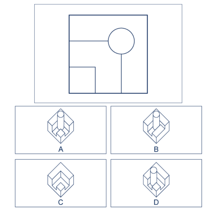
The image presents a spatial reasoning puzzle. It consists of two main sections:
1. A top panel containing a 2D top-down floor plan or layout.
2. A bottom section containing four multiple-choice options (A, B, C, D), each showing a different 3D isometric projection of a structure.
The task implied by the diagram is to identify which of the four 3D structures (A, B, C, or D) correctly corresponds to the given 2D plan.
### Components/Axes
**Top Panel (2D Plan):**
* **Frame:** A large square border.
* **Internal Layout:** A smaller, centered square representing the footprint of a structure.
* **Elements within the footprint:**
* A vertical line dividing the left third from the right two-thirds.
* A horizontal line dividing the top third from the bottom two-thirds.
* A **circle** located in the top-right quadrant formed by the intersecting lines.
* A **square** located in the bottom-left quadrant.
* The lines suggest internal walls or divisions.
**Bottom Panel (3D Options):**
* **Four labeled boxes:** Each contains an isometric drawing of a 3D block structure.
* **Labels:** The letters **A**, **B**, **C**, and **D** are centered below each respective box.
* **Common 3D Elements:** All structures are based on a cube-like base with internal divisions and protruding features. The key differentiating features are:
* A **cylindrical column** (corresponding to the circle in the 2D plan).
* A **rectangular block** (corresponding to the square in the 2D plan).
* The arrangement and presence of internal walls.
### Detailed Analysis
**Analysis of the 2D Plan:**
* The plan shows a square footprint.
* It is divided into four quadrants by a vertical line (left/right) and a horizontal line (top/bottom).
* The **circle** is in the **top-right quadrant**.
* The **square** is in the **bottom-left quadrant**.
* The lines imply that the circle and square are separate features within their respective quadrants, connected to the dividing walls.
**Analysis of the 3D Options:**
* **Option A:**
* Shows a cylindrical column in the **back-right** position (matches top-right in isometric view).
* Shows a rectangular block in the **front-left** position (matches bottom-left in isometric view).
* Has internal walls that appear to create separate compartments for the column and the block.
* **Trend/Verification:** The column is tall and cylindrical. The block is low and rectangular. Their positions align with the 2D plan's quadrants.
* **Option B:**
* Shows a cylindrical column in the **back-right** position.
* Shows a rectangular block in the **front-right** position.
* **Mismatch:** The block is in the wrong quadrant (front-right instead of front-left).
* **Option C:**
* Shows **no cylindrical column**.
* Shows a rectangular block in the **front-left** position.
* **Mismatch:** The prominent circular feature from the 2D plan is entirely absent.
* **Option D:**
* Shows a cylindrical column in the **back-right** position.
* Shows a rectangular block in the **front-left** position.
* **Subtle Difference:** Compared to Option A, the internal wall configuration appears slightly different. In Option A, the wall seems to run from the front of the column to the side of the block. In Option D, the wall configuration is less clear but may connect differently. Option A's wall structure more cleanly separates the two features as implied by the 2D plan's quadrant lines.
### Key Observations
1. **Primary Matching Features:** The correct 3D model must have a cylinder in the back-right (top-right) and a rectangular block in the front-left (bottom-left). This eliminates Options B and C.
2. **Critical Differentiator:** The deciding factor between the plausible Options A and D is the precise configuration of the internal walls. The 2D plan shows clean quadrant divisions. Option A's isometric drawing depicts internal walls that most logically correspond to these divisions, creating distinct spaces for the column and the block. Option D's internal geometry is more ambiguous and less directly mapped.
3. **Spatial Translation:** The puzzle tests the ability to translate a 2D top-down view into a 3D isometric perspective, understanding that "top-right" on the plan becomes "back-right" in the isometric view, and "bottom-left" becomes "front-left".
### Interpretation
This diagram is a classic spatial reasoning test, likely used in aptitude assessments for fields like engineering, architecture, or design. It evaluates the ability to mentally manipulate and rotate objects in three dimensions based on two-dimensional information.
The data (the visual information) suggests that **Option A is the correct answer**. It is the only model that accurately places both key features (cylinder and block) in their correct quadrants *and* presents an internal wall structure that most faithfully represents the quadrant divisions shown in the 2D plan. The anomaly in Option D is its slightly less clear internal wall mapping, making it a less precise translation. The exercise demonstrates that successful 3D reconstruction requires not just matching major features, but also accurately interpreting the relationships and divisions between them.