## Diagram: APTPU Generation Framework
### Overview
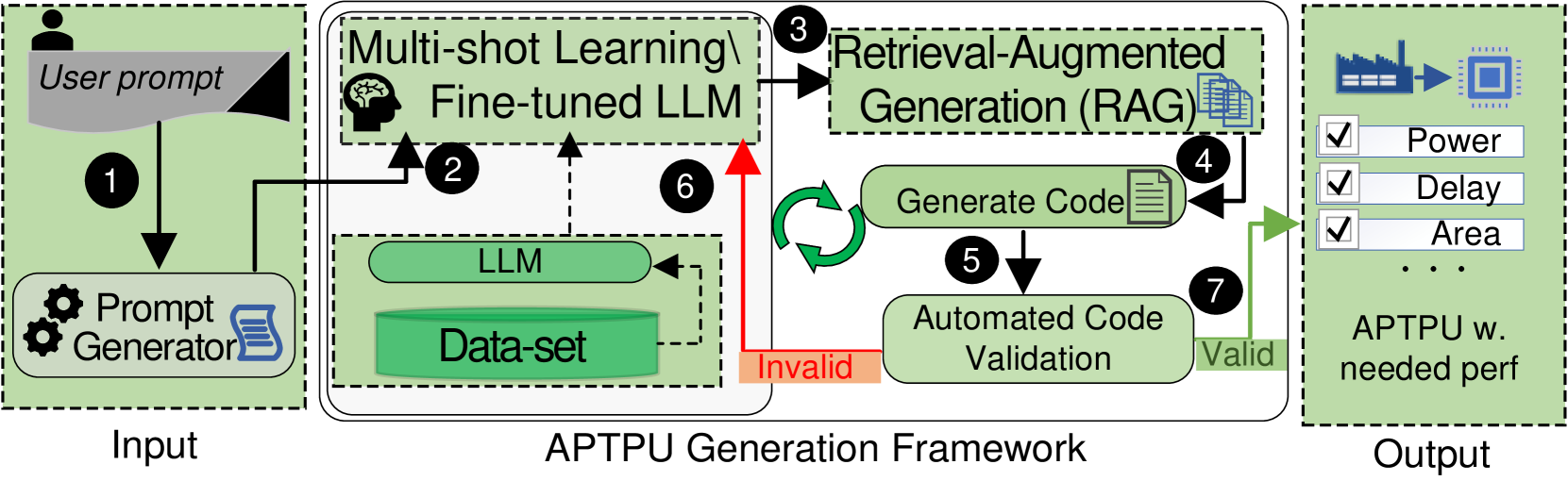
The image is a diagram illustrating the APTPU (Application-Specific Tensor Processing Unit) Generation Framework. It depicts the flow of information and processes involved in generating an APTPU based on user input and validation. The diagram is divided into three main sections: Input, APTPU Generation Framework, and Output.
### Components/Axes
* **Input (Left)**:
* "User prompt" (gray box with a user icon)
* "Prompt Generator" (green box with gear and document icons)
* Arrow labeled "1" indicating the flow from "User prompt" to "Prompt Generator"
* **APTPU Generation Framework (Center)**:
* "Multi-shot Learning\Fine-tuned LLM" (top green box with a brain icon)
* Arrow labeled "2" indicating the flow from "Prompt Generator" to "Multi-shot Learning\Fine-tuned LLM"
* "Retrieval-Augmented Generation (RAG)" (top-right green box with document icons)
* Arrow labeled "3" indicating the flow from "Multi-shot Learning\Fine-tuned LLM" to "Retrieval-Augmented Generation (RAG)"
* "Generate Code" (green box with a document icon)
* Arrow labeled "4" indicating the flow from "Retrieval-Augmented Generation (RAG)" to "Generate Code"
* "Automated Code Validation" (green box)
* Arrow labeled "5" indicating the flow from "Generate Code" to "Automated Code Validation"
* Green circular arrows indicating a loop between "Generate Code" and "Retrieval-Augmented Generation (RAG)"
* "LLM" (green box)
* "Data-set" (green cylinder)
* Red arrow labeled "6" indicating a feedback loop from "Data-set" to "Multi-shot Learning\Fine-tuned LLM"
* "Invalid" (orange box) indicating a negative validation result
* "Valid" (green box) indicating a positive validation result
* Arrow labeled "7" indicating the flow from "Automated Code Validation" to "Valid"
* **Output (Right)**:
* "APTPU w. needed perf" (green box with a factory and chip icon)
* Checkboxes labeled "Power", "Delay", and "Area"
* Ellipsis (...) indicating more parameters
* Arrow indicating the flow from "Valid" to "APTPU w. needed perf"
### Detailed Analysis or Content Details
The diagram illustrates the process of generating an APTPU using a combination of user input, machine learning, and code generation techniques.
1. **Input**: The process starts with a "User prompt" which is then processed by a "Prompt Generator".
2. **Multi-shot Learning/Fine-tuned LLM**: The output of the "Prompt Generator" is fed into a "Multi-shot Learning/Fine-tuned LLM" model.
3. **Retrieval-Augmented Generation (RAG)**: The LLM interacts with a "Retrieval-Augmented Generation (RAG)" module to generate code.
4. **Generate Code**: The RAG module generates code based on the input.
5. **Automated Code Validation**: The generated code is then validated automatically.
6. **Feedback Loop**: If the code is invalid, a feedback loop (indicated by the red arrow labeled "6") sends information back to the "Multi-shot Learning/Fine-tuned LLM" model, potentially using the "Data-set" to refine the model. The green circular arrows indicate a loop between "Generate Code" and "Retrieval-Augmented Generation (RAG)".
7. **Output**: If the code is valid, it leads to the generation of an "APTPU w. needed perf" (APTPU with needed performance), with parameters like "Power", "Delay", and "Area" being considered.
### Key Observations
* The diagram highlights the iterative nature of the APTPU generation process, with a feedback loop for invalid code.
* The use of machine learning (LLM) and retrieval-augmented generation (RAG) is central to the framework.
* The output is an APTPU that meets the required performance specifications.
### Interpretation
The diagram presents a high-level overview of an automated APTPU generation framework. It leverages user prompts, machine learning models, and code generation techniques to create application-specific tensor processing units. The feedback loop ensures that the generated code is validated and refined until it meets the desired performance criteria. The framework aims to automate the design and optimization of APTPUs, potentially reducing the time and effort required for manual design. The inclusion of parameters like "Power", "Delay", and "Area" suggests that the framework considers various performance metrics during the generation process.