## Diagram: Neural Network for Motor Control
### Overview
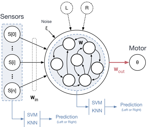
The image depicts a neural network architecture designed for motor control, potentially for a robotic or biological system. It shows the flow of information from sensors through a recurrent neural network to a motor output, with additional prediction outputs using SVM/KNN classifiers.
### Components/Axes
* **Sensors:** A column of sensor inputs labeled S[0], S[i], and S[n], enclosed in a dashed blue box.
* **Recurrent Neural Network (RNN):** A large circle containing smaller circles representing neurons, with recurrent connections indicated by curved arrows. The RNN is shaded light blue and has a dashed blue border. The weight matrix within the RNN is labeled as "w".
* **Noise:** An input labeled "Noise" with the symbol "ξ" (xi).
* **Motor:** A single circle labeled "θ" (theta), representing the motor output.
* **Weights:** Input weights "w_in" and output weights "w_out".
* **Prediction (Left or Right):** Two identical blocks, each consisting of an SVM/KNN classifier and a "Prediction (Left or Right)" output.
* **Inputs L and R:** Two dashed circles labeled "L" and "R" at the top, connected to the RNN with dashed lines.
### Detailed Analysis
* **Sensors:** The sensor inputs are represented as S[0], S[i], and S[n], suggesting a range of sensor values from 0 to n. These sensors feed into the RNN via the input weights "w_in".
* **RNN:** The RNN is the central processing unit. It receives inputs from the sensors, noise, and potentially external signals "L" and "R". The recurrent connections within the RNN allow it to maintain a state and process temporal information.
* **Noise:** The noise input "ξ" introduces randomness into the network, which can help with exploration and robustness.
* **Motor Output:** The motor output "θ" is generated from the RNN via the output weights "w_out". This output likely represents a motor command, such as an angle or velocity.
* **Prediction:** The outputs of the RNN are also fed into two SVM/KNN classifiers. These classifiers are used to predict a binary outcome, "Left or Right".
* **Inputs L and R:** The inputs L and R are connected to the RNN with dashed lines.
### Key Observations
* The diagram highlights the flow of information from sensors to motor output through a recurrent neural network.
* The inclusion of noise and recurrent connections suggests that the network is designed to handle noisy and temporal data.
* The SVM/KNN classifiers provide an additional layer of processing, potentially for decision-making or classification tasks.
* The presence of "L" and "R" inputs suggests that the system might be involved in a left-right decision-making process.
### Interpretation
The diagram illustrates a neural network architecture for motor control that integrates sensory information, internal state, and external signals. The RNN acts as a central processing unit, learning to map sensor inputs to motor outputs. The SVM/KNN classifiers provide an additional layer of processing, potentially for decision-making or classification tasks. The "L" and "R" inputs suggest that the system might be involved in a left-right decision-making process. This architecture could be used in a variety of applications, such as robotics, prosthetics, or autonomous vehicles. The diagram suggests a system capable of learning complex motor control tasks from sensory input, with the ability to make predictions about the environment.