## Diagram: Sensor-Motor Control System with Machine Learning Processing
### Overview
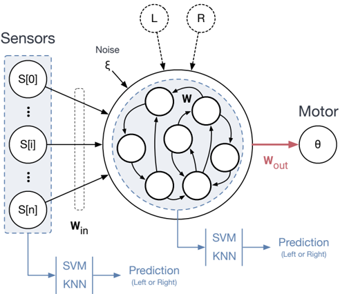
This diagram illustrates a closed-loop control system integrating sensor data, machine learning processing, and motor actuation. The system processes sensor inputs through a computational unit (CPU) containing SVM and KNN models to predict directional decisions (Left/Right), which then control motor movement. Key components include noise injection (ξ), internal weights (w), and output angle (θ).
### Components/Axes
1. **Left Section (Sensors)**:
- Vertical array of labeled sensor inputs: S[0], S[1], ..., S[n]
- Dashed vertical line indicates noise injection point (ξ)
2. **Central Processing Unit (CPU)**:
- Circular boundary containing:
- Internal weights (w) connecting sensor inputs to processing nodes
- Two output arrows labeled "L" (Left) and "R" (Right)
- Dashed boundary indicating processing boundaries
3. **Right Section (Motor)**:
- Output angle (θ) connected to motor
- Weighted output (W_out) in red
4. **Arrows and Flow**:
- Black arrows show data flow from sensors → CPU → motor
- Red arrow specifically highlights motor output (W_out)
### Detailed Analysis
- **Sensor Inputs**:
- Multiple discrete sensors (S[0] to S[n]) provide input data
- Noise (ξ) injected at sensor level before processing
- **CPU Processing**:
- Contains weighted connections (w) between sensor inputs and processing nodes
- Implements two machine learning models:
- SVM KNN (Support Vector Machine + K-Nearest Neighbors)
- Prediction outputs: Left or Right decisions
- Internal processing represented by interconnected nodes
- **Motor Output**:
- Final output angle (θ) controlled by weighted output (W_out)
- Red arrow emphasizes actuation pathway
### Key Observations
1. System architecture follows sensor → processing → actuation flow
2. Dual machine learning models (SVM and KNN) used for directional prediction
3. Noise injection occurs at the sensor level before processing
4. Output angle (θ) is directly controlled by weighted output (W_out)
5. No explicit numerical values provided in diagram
### Interpretation
This diagram represents a hybrid control system combining traditional sensorimotor control with modern machine learning techniques. The integration of SVM and KNN suggests a probabilistic approach to directional decision-making, likely for applications requiring adaptive movement control (e.g., robotics, autonomous systems). The noise injection (ξ) indicates awareness of real-world sensor imperfections, while the weighted connections (w) imply learnable parameters that could be optimized through training. The dual output arrows (L/R) suggest binary decision-making capability, with the motor's angle (θ) representing continuous control output. The system's closed-loop nature implies potential for feedback mechanisms not explicitly shown in this diagram.