\n
## Diagram: Circular Robotic Process Flow
### Overview
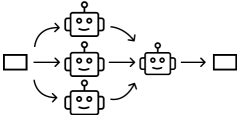
The image depicts a diagram illustrating a circular process flow involving robotic units. The diagram shows four robotic units arranged in a roughly square configuration, with input and output elements connected to the process. Arrows indicate the direction of flow between the units and the input/output.
### Components/Axes
The diagram consists of the following components:
* **Robotic Units:** Four identical robotic units, each represented as a square with a smiling face and a circular connector on top.
* **Input:** A square shape on the left side of the diagram, representing the input to the process.
* **Output:** A square shape on the right side of the diagram, representing the output of the process.
* **Arrows:** Curved arrows indicating the flow of the process between the input, robotic units, and output.
### Detailed Analysis or Content Details
The process flow can be described as follows:
1. Input enters the process and is directed to the top-center robotic unit.
2. The top-center unit passes the process to the right-center unit.
3. The right-center unit passes the process to the bottom-right unit, which outputs the result.
4. The bottom-right unit sends the process to the bottom-left unit.
5. The bottom-left unit sends the process to the top-left unit.
6. The top-left unit sends the process back to the top-center unit, completing the cycle.
There are no numerical values or scales present in the diagram. The diagram is purely illustrative of a process flow.
### Key Observations
The diagram highlights a closed-loop process where the output of one robotic unit becomes the input for another, creating a continuous cycle. The input and output are distinct from the robotic units, suggesting they serve as entry and exit points for the process.
### Interpretation
The diagram likely represents an automated process or workflow where robotic units perform a series of tasks in a cyclical manner. The continuous loop suggests a self-sustaining or iterative process. The input and output elements indicate that the process transforms data or materials from an initial state to a final state. The smiling faces on the robots could indicate a positive or efficient process. The diagram does not provide information about the specific tasks performed by the robots or the nature of the input and output. It is a high-level representation of a process flow, focusing on the relationships between the components rather than the details of the process itself. The diagram could be used to illustrate concepts such as automation, continuous improvement, or feedback loops.