## Technical Diagram and Photograph: Robotic Vehicle Sensor Configuration
### Overview
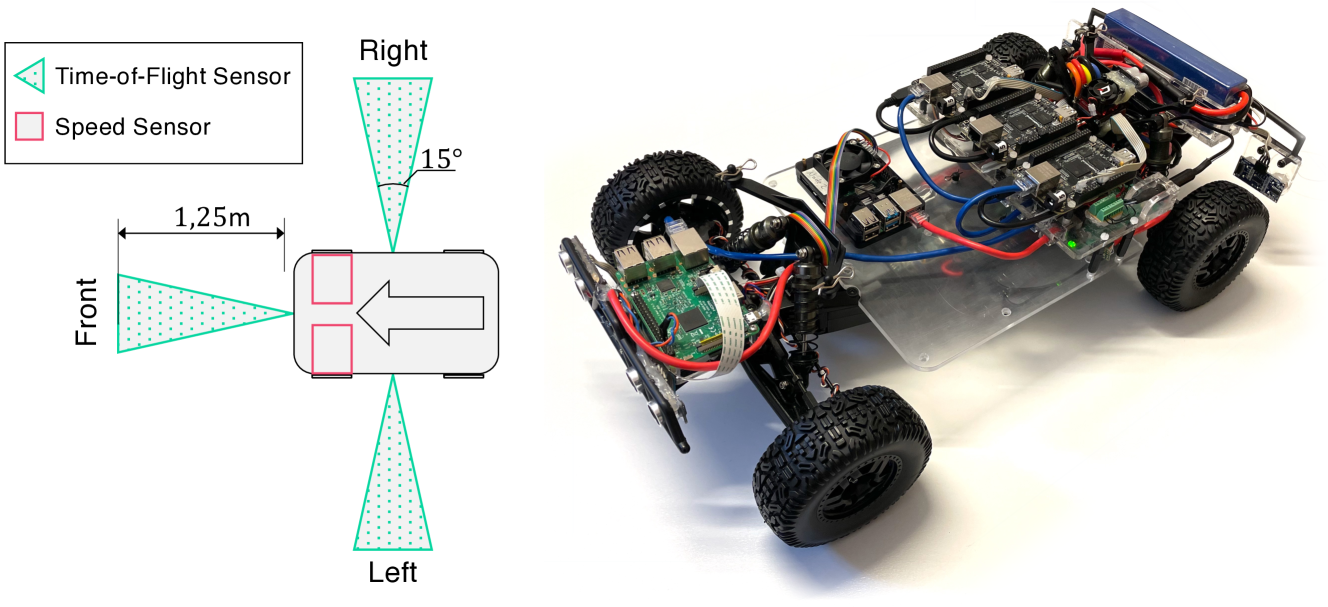
The image is a composite of two parts: a technical schematic diagram on the left and a photograph of a physical robotic vehicle on the right. The diagram illustrates the placement and field of view of sensors on a vehicle platform, while the photograph shows the actual implementation of a similar robotic car.
### Components/Axes
**Left Diagram - Schematic:**
* **Legend (Top-Left):**
* Cyan triangle symbol: "Time-of-Flight Sensor"
* Pink square symbol: "Speed Sensor"
* **Vehicle Diagram (Center):**
* A top-down view of a rectangular vehicle body with rounded corners.
* A large grey arrow inside the vehicle points to the left, indicating the forward direction.
* **Front:** A cyan triangle (Time-of-Flight Sensor) is mounted on the front, projecting a dotted cyan cone forward. The cone's range is labeled "1,25m" (1.25 meters).
* **Right:** A cyan triangle (Time-of-Flight Sensor) is mounted on the right side, projecting a dotted cyan cone sideways. The cone's angular width is labeled "15°".
* **Left:** A cyan triangle (Time-of-Flight Sensor) is mounted on the left side, projecting a dotted cyan cone sideways. No angle is explicitly labeled for this cone, but it is visually symmetric to the right sensor.
* **Speed Sensors:** Two pink squares (Speed Sensors) are mounted on the front axle area, one on each side.
* **Directional Labels:** "Front", "Right", and "Left" are labeled in black text around the vehicle diagram.
**Right Photograph - Physical Robot:**
* **Chassis:** A transparent acrylic or polycarbonate base plate.
* **Wheels:** Four large, black, knobby rubber tires.
* **Electronics:**
* A green Raspberry Pi single-board computer is mounted near the front-left wheel.
* A larger black circuit board (likely a motor controller or main interface board) is mounted centrally.
* A blue lithium polymer (LiPo) battery pack is secured at the rear.
* **Wiring:** A complex network of red, black, blue, and multicolored ribbon cables connects the components.
* **Sensors:** Several small sensor modules are visible, particularly near the front and sides, consistent with the diagram's layout. Their exact type cannot be confirmed from the photo alone.
* **Other Components:** Black suspension components, motor housings, and a front bumper/skid plate.
### Detailed Analysis
**Sensor Configuration (from Diagram):**
* **Time-of-Flight Sensors (Cyan):** Three sensors are deployed for spatial awareness.
1. **Front Sensor:** Has a specified detection range of 1.25 meters directly ahead.
2. **Side Sensors (Left & Right):** Each has a specified field of view of 15 degrees, oriented perpendicular to the vehicle's body for side obstacle detection.
* **Speed Sensors (Pink):** Two sensors are co-located at the front axle, likely for measuring wheel rotation to determine vehicle speed and odometry.
**Physical Implementation (from Photograph):**
* The robot is a custom-built, four-wheel-drive platform.
* The Raspberry Pi suggests it runs a Linux-based operating system for high-level control.
* The central board likely handles power distribution and motor control.
* The sensor placement on the physical robot appears to align with the schematic, with modules visible at the front and sides.
### Key Observations
1. **Diagram-Photo Correlation:** The schematic provides the design intent (sensor types, placement, and specifications), while the photograph shows the practical, assembled result. The physical robot's sensor locations appear consistent with the diagram.
2. **Sensor Specialization:** The design uses different sensor types for different tasks: Time-of-Flight for distance measurement and obstacle detection, and dedicated speed sensors for motion tracking.
3. **Asymmetry in Labeling:** While the left and right Time-of-Flight sensors are drawn symmetrically, only the right sensor's field of view (15°) is explicitly labeled. It is reasonable to assume the left sensor has an identical specification.
4. **Power System:** The presence of a large LiPo battery indicates the robot is designed for untethered, mobile operation.
### Interpretation
This image pair documents the sensor architecture for an autonomous or semi-autonomous ground vehicle. The diagram is a technical specification for sensor integration, defining the robot's perceptual capabilities:
* The **front Time-of-Flight sensor** provides long-range forward detection (1.25m), crucial for navigation and collision avoidance.
* The **side Time-of-Flight sensors** with their 15-degree fields of view enable the robot to perceive its environment laterally, allowing for tasks like wall-following or navigating through narrow passages.
* The **dual front speed sensors** provide redundancy and accuracy for calculating distance traveled (odometry), which is fundamental for localization and motion control.
The photograph validates that this design has been physically realized. The use of a Raspberry Pi points to a research or prototyping context, where flexibility and software control are prioritized. The overall system is designed to give the robot a comprehensive, multi-directional understanding of its immediate surroundings, which is the foundational requirement for any autonomous mobile system. The clear documentation (diagram) alongside the implementation (photo) is typical of engineering projects for reproducibility and analysis.