## Diagram: Feedback Loop Between Two Robotic Components
### Overview
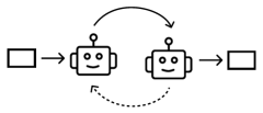
The image depicts a simplified technical diagram illustrating a feedback loop between two identical robotic components. The system includes two input/output blocks (rectangles) and two robot icons connected by directional arrows, forming a cyclical interaction.
### Components/Axes
- **Left Rectangle**: Labeled as an input/output block (no explicit label).
- **Robot A**: Identical to Robot B, featuring a square body, circular head with two eyes, and a single antenna.
- **Robot B**: Mirror image of Robot A, positioned to the right.
- **Right Rectangle**: Labeled as an input/output block (no explicit label).
- **Arrows**:
- Solid arrow from left rectangle → Robot A.
- Solid arrow from Robot A → Robot B.
- Solid arrow from Robot B → right rectangle.
- Dashed bidirectional arrow between Robot A and Robot B, indicating a feedback loop.
### Detailed Analysis
- **Flow Direction**:
1. Data/process flows from the left rectangle into Robot A.
2. Robot A processes the input and sends it to Robot B.
3. Robot B outputs the result to the right rectangle.
4. A feedback mechanism (dashed arrow) allows Robot B to send data back to Robot A, creating a closed-loop system.
- **Component Symmetry**:
Both robots are identical in design, suggesting they perform the same function or represent interchangeable nodes in the system.
### Key Observations
- The feedback loop (dashed arrow) implies iterative processing or real-time adjustment between the two robots.
- The absence of labels on the rectangles leaves their specific roles (e.g., sensor, actuator) ambiguous.
- The simplicity of the diagram prioritizes conceptual clarity over technical detail.
### Interpretation
This diagram likely represents a **closed-loop control system** or **iterative processing pipeline** where two identical components collaborate to refine or stabilize an output. The feedback loop suggests mechanisms for error correction, adaptive learning, or continuous improvement. The lack of explicit labels indicates the diagram is meant to abstractly illustrate a generalizable workflow rather than a specific implementation.
**Notable Design Choices**:
- Use of identical robots emphasizes symmetry and uniformity in the system.
- Dashed feedback arrow visually distinguishes the cyclical interaction from the linear flow.
- Rectangles at both ends imply bidirectional input/output capabilities, though their exact roles are undefined.