## Diagram: Memory and Processing Unit Architectures Comparison
### Overview
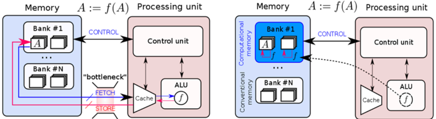
The image presents two side-by-side diagrams comparing memory and processing unit architectures. The left diagram illustrates a conventional architecture with a clear separation between memory banks and processing units, while the right diagram shows a computational memory architecture with integrated processing capabilities. Both diagrams include control units, ALUs (Arithmetic Logic Units), and memory banks, but differ in their data flow and computational capabilities.
### Components/Axes
**Left Diagram (Conventional Architecture):**
- **Memory Section**:
- Contains multiple "Bank #1" to "Bank #N" blocks, each with two square elements.
- Labels: "Memory", "Bank #1", "Bank #N".
- **Processing Unit Section**:
- Contains "Control unit" and "ALU" blocks.
- Labels: "Processing unit", "Control unit", "ALU".
- **Data Flow**:
- Arrows labeled "CONTROL" (blue) connect memory banks to the control unit.
- Arrows labeled "FETCH" (blue) and "STORE" (red) connect the cache to the ALU.
- A "bottleneck" label (red) highlights the fetch/store pathway.
- **Function Notation**: "A := f(A)" appears above the processing unit.
**Right Diagram (Computational Memory Architecture):**
- **Memory Section**:
- Contains "Computational memory" with "Bank #1" to "Bank #N" blocks.
- Labels: "Computational memory", "Bank #1", "Bank #N".
- **Processing Unit Section**:
- Contains "Control unit" and "ALU" blocks.
- Labels: "Processing unit", "Control unit", "ALU".
- **Data Flow**:
- Arrows labeled "CONTROL" (blue) connect computational memory to the control unit.
- Dashed arrows labeled "f" (function application) connect memory banks directly to the ALU.
- No explicit "bottleneck" label.
- **Function Notation**: "A := f(A)" appears above the processing unit.
**Shared Elements**:
- Both diagrams use color-coded arrows:
- Blue: "CONTROL" signals.
- Red: "STORE" operations (left diagram only).
- Pink: "bottleneck" highlight (left diagram only).
- Both include "Cache" blocks connected to the ALU.
### Detailed Analysis
**Left Diagram**:
- Memory banks are isolated from processing units.
- Data must pass through the control unit before reaching the ALU.
- Fetch/store operations create a bottleneck, indicated by the red label and thicker arrow.
- Function application (f(A)) occurs after data retrieval from memory.
**Right Diagram**:
- Memory banks are labeled "Computational memory," implying integrated computation.
- Dashed arrows labeled "f" suggest in-memory computation (A := f(A)).
- No explicit bottleneck, as computation occurs closer to memory.
- Direct data flow from memory to ALU via function application.
### Key Observations
1. **Bottleneck Elimination**: The right diagram removes the fetch/store bottleneck present in the left diagram.
2. **In-Memory Computation**: The right diagram introduces function application (f) directly in memory banks, enabling computation without data movement.
3. **Architectural Integration**: Computational memory in the right diagram blurs the line between storage and processing.
4. **Control Unit Role**: Both architectures retain a central control unit, but its role differs:
- Left: Manages data flow between isolated components.
- Right: Coordinates integrated memory-processing operations.
### Interpretation
The diagrams contrast traditional von Neumann architectures (left) with emerging computational memory designs (right). The left diagram's bottleneck highlights the performance limitations of separating memory and processing. The right diagram's integration of computation into memory banks suggests:
- Reduced latency through in-memory operations.
- Lower energy consumption by minimizing data movement.
- Potential for parallel computation across memory banks.
This architectural shift aligns with trends in neuromorphic and in-memory computing, where processing units are embedded within memory hierarchies to address the "memory wall" problem. The function notation (f(A)) implies support for complex operations directly in memory, which could enable applications like AI/ML workloads with reduced data transfer overhead.