\n
## Diagram: Flowchart with Numbered Nodes
### Overview
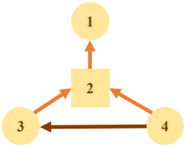
The image depicts a flowchart-style diagram consisting of four nodes, numbered 1 through 4. Node 2 is a square, while nodes 1, 3, and 4 are circles. Arrows indicate the direction of flow or relationships between the nodes. There are no axis labels or legends.
### Components/Axes
The diagram consists of:
* **Node 1:** Circle, labeled "1"
* **Node 2:** Square, labeled "2"
* **Node 3:** Circle, labeled "3"
* **Node 4:** Circle, labeled "4"
* **Arrows:** Indicate flow direction.
### Detailed Analysis or Content Details
The diagram shows the following connections:
* An arrow points from Node 3 to Node 2 (orange).
* An arrow points from Node 4 to Node 2 (orange).
* An arrow points from Node 2 to Node 1 (dark brown).
* An arrow points from Node 4 to Node 3 (dark brown).
### Key Observations
The diagram represents a network of relationships between four elements. Node 2 appears to be a central hub, receiving input from Nodes 3 and 4 and providing output to Node 1. Node 4 also provides input to Node 3. The use of different arrow colors suggests different types of relationships or flows.
### Interpretation
The diagram likely represents a process or system where elements 1, 3, and 4 interact through element 2. The different arrow colors could indicate different types of data or control flow. For example, the orange arrows might represent data flow, while the dark brown arrows represent control signals. Without further context, it's difficult to determine the specific meaning of the diagram. It could represent a simple algorithm, a communication network, or a workflow. The diagram suggests a cyclical relationship between nodes 3 and 4, mediated by node 2. Node 1 is a terminal node, receiving output from node 2.