## Diagram: State Transition Process with Intermediate Computation
### Overview
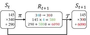
The image displays a technical flowchart or state transition diagram illustrating a three-stage computational process. It shows how an initial state \( S_t \) is transformed via an intermediate computational block \( R_{t+1} \) into a final state \( S_{t+1} \). The diagram uses mathematical notation and arrows to indicate the flow of operations.
### Components/Axes
The diagram consists of three primary rectangular boxes with rounded corners, connected by directional arrows.
1. **Left Box (Initial State):**
* **Label:** \( S_t \) (positioned above the box).
* **Content (transcribed):**
```
145
× 340
+ 290
```
2. **Central Box (Intermediate Computation/Reward):**
* **Label:** \( R_{t+1} \) (positioned above the box).
* **Content (transcribed):**
```
340 → 300
145 × 4 = 580
290 + 5800 = 6090
```
* **Note:** The arrow "→" indicates a transformation or mapping.
3. **Right Box (Final State):**
* **Label:** \( S_{t+1} \) (positioned above the box).
* **Content (transcribed):**
```
145
× 300
+ 6090
```
4. **Connecting Arrows:**
* An arrow labeled **\( \pi \)** (Greek letter pi) points from the right edge of the \( S_t \) box to the left edge of the \( R_{t+1} \) box.
* An arrow labeled **\( T \)** points from the right edge of the \( R_{t+1} \) box to the left edge of the \( S_{t+1} \) box.
### Detailed Analysis
The diagram depicts a sequential transformation of numerical values.
* **From \( S_t \) to \( R_{t+1} \) (via \( \pi \)):**
* The value `340` from the multiplication line in \( S_t \) is transformed to `300` in the first line of \( R_{t+1} \).
* A new computation is introduced: `145 × 4 = 580`. The multiplicand `145` matches the first number in \( S_t \).
* Another computation is shown: `290 + 5800 = 6090`. The addend `290` matches the last number in \( S_t \). However, the source of the value `5800` is not explicitly derived from the previous line (`580`). This is a notable inconsistency or potential error in the diagram's internal logic.
* **From \( R_{t+1} \) to \( S_{t+1} \) (via \( T \)):**
* The first number `145` is carried over unchanged from \( S_t \) through \( R_{t+1} \) to \( S_{t+1} \).
* The transformed multiplier `300` (from `340 → 300` in \( R_{t+1} \)) becomes the new multiplier in \( S_{t+1} \).
* The computed sum `6090` (from `290 + 5800` in \( R_{t+1} \)) becomes the new addend in \( S_{t+1} \).
### Key Observations
1. **Value Persistence:** The number `145` remains constant throughout all three stages.
2. **Value Transformation:** The multiplier changes from `340` to `300`. The addend changes dramatically from `290` to `6090`.
3. **Internal Inconsistency:** The computation `290 + 5800 = 6090` within \( R_{t+1} \) uses the value `5800`, which is not the result of the immediately preceding line (`145 × 4 = 580`). This suggests either a typo (where `5800` should be `580`, making the sum `870`) or that `5800` is an external input not shown in the flow.
4. **Symbolic Flow:** The labels \( \pi \) and \( T \) are common in reinforcement learning and control theory, often representing a *policy* and a *transition function*, respectively. This context suggests the diagram models a decision-making or state-update process.
### Interpretation
This diagram likely represents a single step in an iterative algorithm, such as those found in dynamic programming or reinforcement learning.
* **What it demonstrates:** It shows how a state \( S_t \), defined by a set of parameters (145, 340, 290), is processed. A policy \( \pi \) generates an intermediate result \( R_{t+1} \), which involves modifying one parameter (340→300) and performing auxiliary calculations. A transition function \( T \) then uses these results to compute the next state \( S_{t+1} \), updating the parameters to (145, 300, 6090).
* **Relationships:** The process is linear and causal. \( R_{t+1} \) acts as a computational workspace that depends on \( S_t \) and determines \( S_{t+1} \). The unchanged value `145` may represent a fixed feature of the environment or agent.
* **Notable Anomaly:** The discrepancy between `580` and `5800` is critical. If `5800` is correct, it implies a large, unexplained external input. If it is a typo for `580`, then the final state \( S_{t+1} \) would be (145, 300, 870), which is a much smaller update. The current diagram, as drawn, contains a logical gap in the data flow.