## Diagram: Communication Policy Network
### Overview
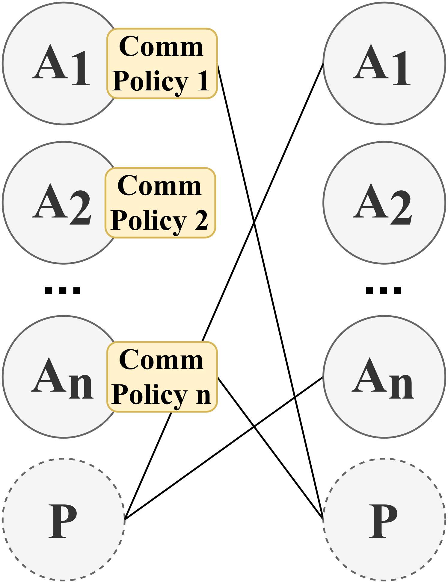
The image is a schematic diagram illustrating a network of communication policies connecting two sets of entities. It depicts a one-to-many or many-to-many relationship where specific policies on the left side are linked to multiple entities on the right side. The diagram uses circles to represent entities and labeled boxes to represent policies, with lines indicating connections.
### Components/Axes
The diagram is organized into two vertical columns of circular nodes, with policy labels attached to the left column.
**Left Column (Top to Bottom):**
1. **Circle A1:** Solid gray border, containing the text "A1".
2. **Circle A2:** Solid gray border, containing the text "A2".
3. **Ellipsis (...):** Three black squares indicating a sequence continues (A3, A4, etc.).
4. **Circle An:** Solid gray border, containing the text "An".
5. **Circle P:** Dashed gray border, containing the text "P".
**Attached Policy Labels (Left Column):**
* A yellow, rounded rectangle with a thin black border is attached to the right side of each solid-bordered circle (A1, A2, An).
* **Label on A1:** "Comm Policy 1"
* **Label on A2:** "Comm Policy 2"
* **Label on An:** "Comm Policy n"
**Right Column (Top to Bottom):**
1. **Circle A1:** Solid gray border, containing the text "A1".
2. **Circle A2:** Solid gray border, containing the text "A2".
3. **Ellipsis (...):** Three black squares indicating a sequence continues.
4. **Circle An:** Solid gray border, containing the text "An".
5. **Circle P:** Dashed gray border, containing the text "P".
**Connections (Lines):**
Black lines originate from the yellow policy boxes and connect to circles in the right column.
* **From "Comm Policy 1":** A line connects to the right-column circle **A1**.
* **From "Comm Policy 2":** A line connects to the right-column circle **P**.
* **From "Comm Policy n":** Two lines originate from this box:
* One line connects to the right-column circle **A2**.
* Another line connects to the right-column circle **P**.
### Detailed Analysis
The diagram establishes a clear mapping:
* **Entity Types:** There are two types of entities: "A" types (A1, A2, ..., An) and a "P" type. The "P" type is visually distinguished by a dashed border.
* **Policy Assignment:** Each "A" entity on the left (A1, A2, An) is assigned a specific, numbered communication policy ("Comm Policy 1", "Comm Policy 2", "Comm Policy n").
* **Connection Logic:** The policies dictate connections to entities on the right. The connections are not strictly one-to-one:
* Policy 1 connects only to its namesake (A1).
* Policy 2 connects to a different entity type (P).
* Policy n connects to two entities: one "A" type (A2) and the "P" type.
* **Spatial Layout:** The policy boxes are positioned to the immediate right of their source circles. The connection lines cross the central space diagonally to reach their target circles in the right column.
### Key Observations
1. **Asymmetric Connections:** The connection pattern is not uniform. "Comm Policy 1" has a direct, self-referential link, while "Comm Policy n" has divergent links to two different entities.
2. **Role of Entity P:** The entity "P" (dashed circle) is a common connection point, receiving links from both "Comm Policy 2" and "Comm Policy n". This suggests "P" may be a central, privileged, or different class of agent (e.g., a Primary agent, a Process, or a Policy server).
3. **Generalization:** The use of "n" and ellipses (...) indicates this is a generalized model for an arbitrary number of "A" entities and their associated policies.
### Interpretation
This diagram models a system where individual agents or components (A1 through An) are governed by distinct communication policies. These policies determine their interaction partners within a network.
The data suggests a flexible or complex communication architecture:
* **Specialization:** Agents may have specialized roles, as different policies lead to different connection targets.
* **Centralization:** The frequent connection to the "P" entity implies a centralized component that multiple policies interact with, possibly for coordination, authentication, or logging.
* **Policy-Driven Networking:** The core concept is that communication pathways are not hardcoded between agents but are dynamically defined by the policies assigned to them. This is common in multi-agent systems, network security models, or microservice architectures where policy engines control service-to-service communication.
The diagram effectively conveys that understanding the system requires knowing both the assignment of policies to source agents and the specific connection rules encoded within each policy.