## Diagram: Memory Access Flow
### Overview
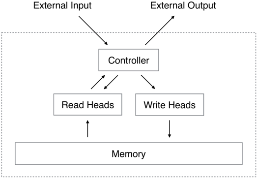
The image is a diagram illustrating the flow of data and control in a memory access system. It shows the interaction between external input/output, a controller, read/write heads, and memory. The diagram uses arrows to indicate the direction of data flow and control signals.
### Components/Axes
* **External Input:** Located at the top-left of the diagram.
* **External Output:** Located at the top-right of the diagram.
* **Controller:** Located centrally at the top of the diagram.
* **Read Heads:** Located centrally on the left side of the diagram.
* **Write Heads:** Located centrally on the right side of the diagram.
* **Memory:** Located at the bottom of the diagram.
* A dashed rectangle surrounds all components except "External Input" and "External Output".
### Detailed Analysis
* **External Input** has an arrow pointing downwards to the **Controller**.
* **External Output** has an arrow pointing upwards and away from the **Controller**.
* The **Controller** has two arrows pointing downwards, one to **Read Heads** and one to **Write Heads**.
* The **Controller** has two arrows pointing upwards and to the left, towards the **Read Heads**.
* **Read Heads** has an arrow pointing upwards from **Memory**.
* **Write Heads** has an arrow pointing downwards to **Memory**.
### Key Observations
* The diagram illustrates a system where external input is processed by a controller, which then directs read and write operations to memory via read and write heads.
* The controller receives input and provides output, and also controls the read and write heads.
* The read heads retrieve data from memory, while the write heads store data into memory.
* The dashed rectangle likely represents the boundary of the system or a specific module.
### Interpretation
The diagram represents a simplified model of a memory access system. The controller acts as the central processing unit, receiving external input and generating external output. It manages the flow of data between memory and the external environment by controlling the read and write heads. The two-way arrows between the controller and read heads suggest that the controller receives feedback or status information from the read heads. The dashed rectangle likely represents the boundary of the memory subsystem or a specific hardware component. This diagram is useful for understanding the basic architecture and data flow within a memory system.