## Diagram: Octree-GS Pipeline and Anchor Initialization
### Overview
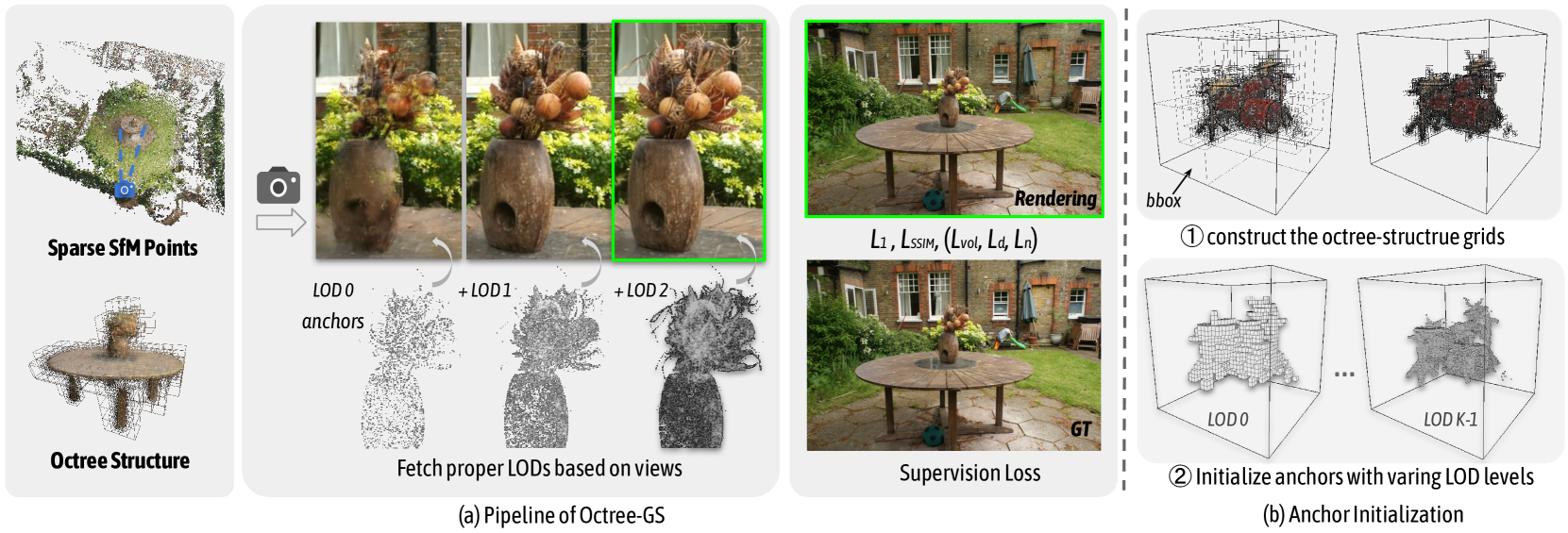
The image presents a diagram illustrating the pipeline of Octree-GS and anchor initialization. It shows the process of generating a 3D representation from sparse SfM points, refining it through different Levels of Detail (LODs), and initializing anchors for further processing.
### Components/Axes
* **Sparse SfM Points:** A point cloud representation of a scene, likely generated using Structure from Motion (SfM) techniques.
* **Octree Structure:** A hierarchical tree structure used to partition 3D space, enabling efficient storage and processing of 3D data.
* **Camera Icon (O\*)**: Represents the camera's viewpoint.
* **LOD 0 anchors, +LOD 1, +LOD 2:** Different levels of detail for the 3D representation.
* **Rendering:** A rendered image of the 3D scene.
* **GT:** Ground Truth image of the scene.
* **L1, LSSIM, (Lvol, Ld, Ln):** Loss functions used for supervision.
* **bbox:** Bounding box.
* **LOD 0, LOD K-1:** Level of detail 0 and Level of detail K-1.
### Detailed Analysis
The diagram is divided into two main parts, labeled (a) and (b).
**(a) Pipeline of Octree-GS:**
1. **Sparse SfM Points:** The process begins with a sparse point cloud.
2. **Camera Viewpoint (O\*)**: An arrow indicates the camera's viewpoint.
3. **LOD Refinement:** The point cloud is refined through different levels of detail (LOD 0, +LOD 1, +LOD 2). The images show the progression of detail as the LOD increases.
4. **Rendering:** A rendered image is generated from the refined 3D representation. This rendering is enclosed in a green box.
5. **Ground Truth (GT):** A ground truth image of the scene is provided for comparison.
6. **Supervision Loss:** Loss functions (L1, LSSIM, (Lvol, Ld, Ln)) are used to supervise the training process.
The text "Fetch proper LODs based on views" is placed below the LOD refinement images, indicating that the appropriate level of detail is selected based on the viewpoint.
**(b) Anchor Initialization:**
1. **Construct the octree-structure grids:** The first step involves constructing octree grids within a bounding box (bbox).
2. **Initialize anchors with varying LOD levels:** Anchors are initialized with varying levels of detail, ranging from LOD 0 to LOD K-1.
### Key Observations
* The diagram illustrates a pipeline for generating and refining 3D representations from sparse point clouds.
* Octree structures and LODs are used to efficiently represent and process 3D data.
* Supervision loss functions are used to guide the training process.
* Anchor initialization is performed using varying LOD levels.
### Interpretation
The diagram describes a method for generating 3D representations of scenes from sparse point clouds. The Octree-GS pipeline uses octree structures and LODs to efficiently represent and process the 3D data. The anchor initialization process prepares the data for further processing, such as object detection or scene understanding. The use of supervision loss functions ensures that the generated 3D representations are accurate and consistent with the ground truth.