\n
## Chart: Average Success Probability vs. Saturation Parameter
### Overview
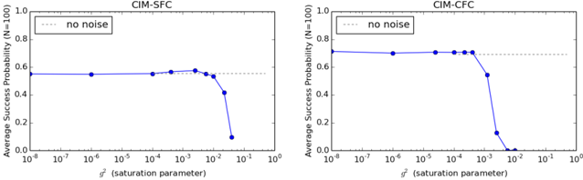
The image presents two charts, side-by-side, displaying the relationship between Average Success Probability and a saturation parameter (denoted as 𝜚²). Both charts include a reference line representing the "no noise" condition. The charts are labeled "CIM-SFC" and "CIM-CFC" respectively. Both charts have the same y-axis scale and x-axis scale.
### Components/Axes
* **X-axis:** Labeled "𝜚² (saturation parameter)". The scale is logarithmic, ranging from 10⁻⁸ to 10⁰.
* **Y-axis:** Labeled "Average Success Probability (N=100)". The scale ranges from 0.0 to 1.0.
* **Legend (Top-Left of each chart):**
* "no noise" - Represented by a dotted gray line.
* **Data Series:** A single blue line representing the Average Success Probability for a given saturation parameter.
### Detailed Analysis
**Chart 1: CIM-SFC**
The blue line in the CIM-SFC chart initially remains relatively flat, hovering around 0.55, from approximately 10⁻⁸ to 10⁻³ on the x-axis. Around 10⁻³ the line begins to descend sharply.
* **Approximate Data Points:**
* 𝜚² = 10⁻⁸: Average Success Probability ≈ 0.56
* 𝜚² = 10⁻⁷: Average Success Probability ≈ 0.56
* 𝜚² = 10⁻⁶: Average Success Probability ≈ 0.56
* 𝜚² = 10⁻⁵: Average Success Probability ≈ 0.55
* 𝜚² = 10⁻⁴: Average Success Probability ≈ 0.54
* 𝜚² = 10⁻³: Average Success Probability ≈ 0.48
* 𝜚² = 10⁻²: Average Success Probability ≈ 0.35
* 𝜚² = 10⁻¹: Average Success Probability ≈ 0.12
* 𝜚² = 10⁰: Average Success Probability ≈ 0.03
The dotted gray "no noise" line is positioned horizontally at approximately 0.58.
**Chart 2: CIM-CFC**
The blue line in the CIM-CFC chart is initially flat, around 0.65, from approximately 10⁻⁸ to 10⁻³ on the x-axis. Around 10⁻³ the line begins to descend sharply.
* **Approximate Data Points:**
* 𝜚² = 10⁻⁸: Average Success Probability ≈ 0.66
* 𝜚² = 10⁻⁷: Average Success Probability ≈ 0.66
* 𝜚² = 10⁻⁶: Average Success Probability ≈ 0.66
* 𝜚² = 10⁻⁵: Average Success Probability ≈ 0.65
* 𝜚² = 10⁻⁴: Average Success Probability ≈ 0.64
* 𝜚² = 10⁻³: Average Success Probability ≈ 0.55
* 𝜚² = 10⁻²: Average Success Probability ≈ 0.35
* 𝜚² = 10⁻¹: Average Success Probability ≈ 0.12
* 𝜚² = 10⁰: Average Success Probability ≈ 0.03
The dotted gray "no noise" line is positioned horizontally at approximately 0.58.
### Key Observations
* Both charts exhibit a similar trend: a relatively stable Average Success Probability at low saturation parameters, followed by a rapid decline as the saturation parameter increases.
* The "no noise" line provides a baseline for comparison. The Average Success Probability drops below this baseline as the saturation parameter increases, indicating a degradation in performance due to the saturation effect.
* The CIM-CFC chart maintains a higher Average Success Probability than the CIM-SFC chart for most of the saturation parameter range.
### Interpretation
The charts demonstrate the impact of the saturation parameter (𝜚²) on the Average Success Probability of two different methods, CIM-SFC and CIM-CFC. The saturation parameter appears to introduce noise or instability, leading to a decrease in success probability. The "no noise" line represents the theoretical maximum success probability in the absence of this saturation effect.
The fact that both charts show a similar trend suggests that the saturation effect is a fundamental limitation of the underlying process. The difference in initial success probability between CIM-SFC and CIM-CFC indicates that CIM-CFC is more robust to the saturation effect, maintaining a higher success rate for a wider range of saturation parameters. The sharp decline in success probability at higher saturation parameters suggests a critical threshold beyond which the methods become unreliable. The logarithmic scale of the x-axis highlights the sensitivity of the success probability to changes in the saturation parameter at lower values.