\n
## Diagram: Memristor Dynamics - Volatile vs. Non-Volatile
### Overview
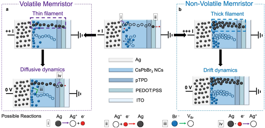
The image presents a comparative diagram illustrating the dynamics of volatile and non-volatile memristors. It depicts the structural changes and ion movement within these devices under different voltage conditions. The diagram is split into two main sections (a and b), representing volatile and non-volatile memristors respectively. Each section shows a series of states representing the device's behavior under positive voltage, zero voltage, and the resulting dynamics. A legend at the bottom explains the symbols used to represent ions and vacancies.
### Components/Axes
The diagram consists of layered structures representing the memristor components. These layers are labeled as follows:
* **Ag:** Silver
* **CsPbBr3 NCs:** Cesium Lead Bromide Nanocrystals
* **pTPD:** (likely an organic semiconductor)
* **PEDOT:PSS:** Poly(3,4-ethylenedioxythiophene) polystyrene sulfonate
* **ITO:** Indium Tin Oxide
The diagram also uses symbols to represent ions and vacancies:
* **i:** Ag⁺ + e⁻ (Silver ion plus electron) - Red circle with a plus sign and an electron.
* **ii:** Ag⁺ → Ag (Silver ion transforms to Silver) - Red circle transforming into a black circle.
* **iii:** Br⁻ (Bromide ion) - Blue circle.
* **iv:** VBr (Bromide vacancy) - Yellow circle.
Voltage sources are indicated with "+" and "-" signs, and arrows show the direction of ion movement.
### Detailed Analysis / Content Details
**Section a: Volatile Memristor - Thin Filament**
* **Initial State (Top-Left):** A positive voltage is applied to the structure. Silver ions (Ag⁺, represented by red circles) and electrons (e⁻) are present.
* **Intermediate State (Top-Center):** Silver ions are reduced to silver atoms (Ag, represented by black circles), forming a thin filament. The reaction i (Ag⁺ + e⁻ → Ag) is indicated.
* **Intermediate State (Top-Right):** The filament continues to grow with more silver atoms.
* **Final State (Bottom-Left):** When the voltage is set to 0V, the silver atoms exhibit diffusive dynamics. Silver atoms are shown moving randomly within the structure.
* **Final State (Bottom-Center):** Silver atoms are shown moving randomly within the structure. The reaction iii (Br⁻) is indicated.
* **Final State (Bottom-Right):** Silver atoms are shown moving randomly within the structure. The reaction iv (Ag e⁻ Ag⁺) is indicated.
**Section b: Non-Volatile Memristor - Thick Filament**
* **Initial State (Top-Left):** A positive voltage is applied to the structure. Silver ions (Ag⁺, represented by red circles) and electrons (e⁻) are present.
* **Intermediate State (Top-Center):** Silver ions are reduced to silver atoms (Ag, represented by black circles), forming a thick filament. The reaction i (Ag⁺ + e⁻ → Ag) is indicated.
* **Intermediate State (Top-Right):** The filament continues to grow with more silver atoms.
* **Final State (Bottom-Left):** When the voltage is set to 0V, the silver atoms exhibit drift dynamics. Silver atoms are shown moving in a directed manner within the structure.
* **Final State (Bottom-Center):** Silver atoms are shown moving in a directed manner within the structure. The reaction iii (Br⁻) is indicated.
* **Final State (Bottom-Right):** Silver atoms are shown moving in a directed manner within the structure. The reaction iv (Ag e⁻ Ag⁺) is indicated.
### Key Observations
The key difference between the volatile and non-volatile memristors lies in the dynamics of the silver atoms when the voltage is removed. In the volatile memristor, the silver atoms exhibit diffusive dynamics (random movement), leading to filament dissolution and loss of memory. In the non-volatile memristor, the silver atoms exhibit drift dynamics (directed movement), maintaining the filament structure and preserving the memory state. The filament in the non-volatile memristor is also depicted as being thicker than in the volatile memristor.
### Interpretation
This diagram illustrates the fundamental mechanisms governing the volatility of memristors. The type of ion dynamics (diffusive vs. drift) is directly linked to the stability of the conductive filament and, consequently, the memory retention capability of the device. The thicker filament in the non-volatile memristor likely contributes to its stability by providing more anchoring points and reducing the likelihood of complete dissolution. The reactions i, ii, iii, and iv represent the electrochemical processes involved in the formation and dissolution of the silver filament, driven by the applied voltage and the movement of ions and vacancies within the material. The diagram provides a visual explanation of how material properties and ion dynamics can be engineered to create memristors with desired volatility characteristics. The diagram is a conceptual illustration and does not provide quantitative data. It focuses on the qualitative differences in behavior.