## Diagram: Neural Network for Relation Extraction
### Overview
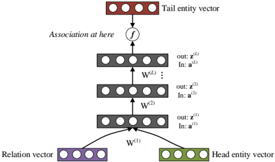
The image depicts a neural network architecture designed for relation extraction between entities. It illustrates the flow of information from input vectors representing a relation and a head entity, through multiple layers of the network, to an output vector representing the tail entity.
### Components/Axes
* **Input Layer:**
* **Relation vector:** Located at the bottom-left, represented by a purple rectangle containing four circles.
* **Head entity vector:** Located at the bottom-right, represented by a green rectangle containing four circles.
* **Hidden Layers:** Three layers of nodes, each represented by a gray rectangle containing four circles.
* Layer 1: Labeled with "out: z^(1)" and "In: a^(1)" to the right.
* Layer 2: Labeled with "out: z^(2)" and "In: a^(2)" to the right.
* Layer L: Labeled with "out: z^(L)" and "In: a^(L)" to the right.
* **Output Layer:**
* **Tail entity vector:** Located at the top, represented by a brown rectangle containing four circles.
* **Weights:**
* W^(1): Connects the input layer to the first hidden layer.
* W^(2): Connects the first hidden layer to the second hidden layer.
* W^(L): Connects the second hidden layer to the output layer.
* **Association Function:** A circle containing the letter "f" is positioned between the last hidden layer and the output layer, labeled "Association at here".
### Detailed Analysis
The diagram shows a feedforward neural network. The relation vector and head entity vector are fed into the network. These vectors are then passed through multiple hidden layers. Each layer applies a weight matrix (W^(1), W^(2), W^(L)) and an activation function (implicitly) to the input from the previous layer. The output of the final hidden layer is then passed through an association function "f" to produce the tail entity vector.
* **Relation vector:** Purple rectangle, bottom-left.
* **Head entity vector:** Green rectangle, bottom-right.
* **Hidden Layers:** Three gray rectangles, stacked vertically.
* **Tail entity vector:** Brown rectangle, top.
* **Connections:** Arrows indicate the flow of information between layers.
* **Weights:** W^(1), W^(2), and W^(L) are labeled on the arrows connecting the layers.
* **Association Function:** "f" is labeled above the arrow connecting the last hidden layer to the tail entity vector.
### Key Observations
* The network architecture is a multi-layer perceptron (MLP).
* The input consists of two vectors: a relation vector and a head entity vector.
* The output is a tail entity vector.
* The network learns to associate the relation and head entity with the tail entity.
### Interpretation
This diagram illustrates a neural network model for predicting the tail entity given a head entity and the relation between them. The network learns to represent the relationships between entities in a vector space. The multiple hidden layers allow the network to learn complex, non-linear relationships between the input and output vectors. The association function "f" likely represents a final transformation or classification step to produce the tail entity vector. The model can be used for tasks such as knowledge graph completion, where the goal is to predict missing relationships between entities.