## Diagram: Data-steering and Multiply-Accumulate Hardware
### Overview
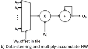
The image presents a block diagram illustrating data-steering and multiply-accumulate hardware. It shows how input data is selected, multiplied by a weight, and then accumulated to produce an output.
### Components/Axes
* **Inputs:** A0, A1, ..., Af (representing multiple input data lines)
* **Multiplexer:** A block that selects one of the input data lines based on the "Wi's offset in tile" signal.
* **Multiplier:** Represented by a circle with an "X" inside. It multiplies the selected input data with the weight Wi.
* **Accumulator:** Represented by a circle with a "+" inside. It adds the result of the multiplication to the previous accumulated value.
* **Weight Input:** Wi (representing the weight value)
* **Offset Input:** Wi's offset in tile (controls the multiplexer)
* **Output:** O0 (representing the final output)
* **Feedback Loop:** A loop connecting the output of the accumulator back to its input, enabling accumulation.
### Detailed Analysis
1. **Input Selection:** The inputs A0, A1, up to Af are fed into a multiplexer. The multiplexer selects one of these inputs based on the "Wi's offset in tile" signal.
2. **Multiplication:** The selected input from the multiplexer is then multiplied by the weight Wi using the multiplier.
3. **Accumulation:** The result of the multiplication is added to the previous accumulated value using the accumulator. The accumulator's output is fed back into its input, creating a feedback loop.
4. **Output:** The final accumulated value is output as O0.
### Key Observations
* The diagram illustrates a common hardware architecture used in neural networks and digital signal processing for performing multiply-accumulate operations.
* The "Wi's offset in tile" signal is crucial for selecting the appropriate input data for processing.
* The feedback loop in the accumulator enables the accumulation of multiple multiplication results.
### Interpretation
The diagram demonstrates how data-steering and multiply-accumulate operations are implemented in hardware. The multiplexer selects the appropriate input data, which is then multiplied by a weight and accumulated. This architecture is commonly used in applications such as neural networks, where multiple inputs need to be processed and combined to produce an output. The "Wi's offset in tile" signal allows for flexible data selection, while the feedback loop in the accumulator enables the accumulation of multiple multiplication results.