\n
## Diagram: Binaural Sound Source Localization System
### Overview
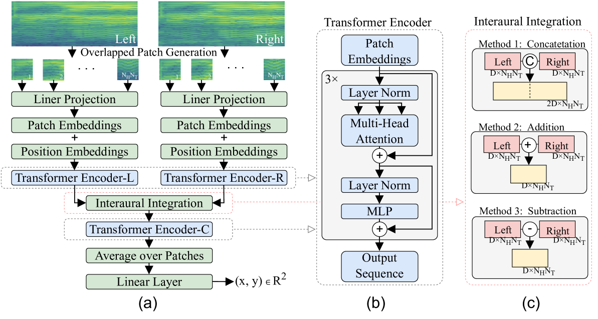
This diagram illustrates a system for binaural sound source localization, likely using a transformer-based architecture. It depicts three main components: (a) the processing pipeline for left and right ear signals, (b) a transformer encoder block, and (c) methods for interaural integration. The overall goal appears to be to estimate the 2D coordinates (x, y) of a sound source based on input from two ears.
### Components/Axes
The diagram is divided into three sections labeled (a), (b), and (c).
* **(a) Left/Right Processing Pipeline:** This section shows the processing steps for the left and right ear signals separately. Key components include "Overlapped Patch Generation", "Liner Projection", "Patch Embeddings + Position Embeddings", "Transformer Encoder-L/R", "Interaural Integration", "Transformer Encoder-C", "Average over Patches", and "Linear Layer".
* **(b) Transformer Encoder:** This section details the internal structure of the transformer encoder used in the system. It includes "Patch Embeddings", "Layer Norm", "Multi-Head Attention", "MLP", and "Output Sequence".
* **(c) Interaural Integration:** This section presents three methods for combining the information from the left and right ears: "Concatenation", "Addition", and "Subtraction".
The dimensions `N<sub>H</sub>`, `N<sub>T</sub>`, and `D` are used in the diagram, representing parameters of the input data and embedding spaces. The output of the linear layer is specified as `(x, y) ∈ R<sup>2</sup>`, indicating a 2D coordinate output.
### Detailed Analysis or Content Details
**(a) Left/Right Processing Pipeline:**
* **Overlapped Patch Generation:** Input signals are divided into overlapping patches. The patch size is indicated as `N<sub>H</sub> x N<sub>T</sub>`.
* **Liner Projection:** The patches are projected into an embedding space.
* **Patch Embeddings + Position Embeddings:** Patch embeddings are combined with positional embeddings.
* **Transformer Encoder-L/R:** The combined embeddings are processed by a transformer encoder for the left and right ears respectively.
* **Interaural Integration:** The outputs of the left and right transformer encoders are integrated using one of the methods described in (c).
* **Transformer Encoder-C:** The integrated representation is further processed by another transformer encoder.
* **Average over Patches:** The output of the second transformer encoder is averaged over all patches.
* **Linear Layer:** The averaged representation is passed through a linear layer to produce the final 2D coordinates (x, y).
**(b) Transformer Encoder:**
* **Patch Embeddings:** Input to the transformer encoder.
* **Layer Norm:** Normalization layer applied to the embeddings.
* **Multi-Head Attention:** Attention mechanism to capture relationships between patches.
* **Addition:** Residual connection, adding the input to the output of the attention mechanism.
* **Layer Norm:** Another normalization layer.
* **MLP:** Multi-Layer Perceptron for further processing.
* **Addition:** Residual connection, adding the input to the output of the MLP.
* **Output Sequence:** The final output of the transformer encoder.
**(c) Interaural Integration:**
* **Method 1: Concatenation:** The left and right ear representations (each of dimension `D x N<sub>H</sub> x N<sub>T</sub>`) are concatenated, resulting in a combined representation of dimension `2D x N<sub>H</sub> x N<sub>T</sub>`.
* **Method 2: Addition:** The left and right ear representations are added element-wise, resulting in a combined representation of dimension `D x N<sub>H</sub> x N<sub>T</sub>`.
* **Method 3: Subtraction:** The left and right ear representations are subtracted element-wise, resulting in a combined representation of dimension `D x N<sub>H</sub> x N<sub>T</sub>`.
### Key Observations
* The system utilizes a dual-path architecture, processing left and right ear signals independently before integrating them.
* Transformer encoders are used extensively for feature extraction and representation learning.
* Three different methods for interaural integration are proposed, offering flexibility in how the information from the two ears is combined.
* The final output is a 2D coordinate, suggesting the system aims to localize the sound source in a plane.
* The use of overlapping patches suggests a time-frequency representation of the audio signal.
### Interpretation
This diagram describes a sophisticated system for binaural sound source localization. The use of transformers suggests the system is capable of capturing long-range dependencies in the audio signal, which is crucial for accurate localization. The three interaural integration methods provide options for different types of sound cues (e.g., interaural time difference, interaural level difference). The system likely leverages the differences in arrival time and intensity of sound at the two ears to estimate the source's location. The final linear layer maps the learned representation to a 2D coordinate, providing a spatial estimate of the sound source. The choice of which interaural integration method to use could depend on the specific acoustic environment and the characteristics of the sound source. The diagram does not provide information about the training data or the specific implementation details of the transformer encoders, but it outlines a promising architecture for binaural sound source localization.