\n
## Diagram: Electrochemical Filament Formation and Dynamics
### Overview
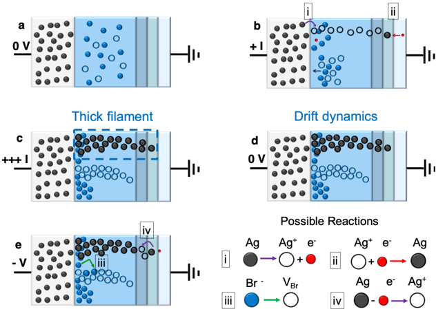
The image presents a schematic diagram illustrating the formation and dynamics of a silver (Ag) filament within an electrolyte, likely a solid-state electrolyte, under varying applied voltages. The diagram consists of five panels (a-e) depicting different stages of the process, along with a "Possible Reactions" key explaining the chemical processes involved. The panels show the distribution of silver ions (Ag⁺, represented by grey circles), silver atoms (Ag, represented by black circles), bromide ions (Br⁻, represented by blue circles), and electrons (e⁻). Each panel also includes a schematic representation of electrodes with applied voltage indicated.
### Components/Axes
The diagram does not have traditional axes. Instead, it uses visual representations of components within a cell:
* **Electrode:** Represented by vertical lines on the right and left sides of each panel.
* **Electrolyte:** The blue shaded region between the electrodes.
* **Silver Ions (Ag⁺):** Grey circles.
* **Silver Atoms (Ag):** Black circles.
* **Bromide Ions (Br⁻):** Blue circles.
* **Electrons (e⁻):** Not explicitly shown as circles, but indicated in the "Possible Reactions" key.
* **Voltage:** Indicated numerically next to the electrodes (0V, +1, +++, -V).
* **Arrows:** Indicate movement or reaction direction.
* **Labels:** i, ii, iii, iv are used to label specific reactions in the "Possible Reactions" key.
### Detailed Analysis or Content Details
**Panel a (0V):**
* Silver ions (grey) and bromide ions (blue) are distributed randomly within the electrolyte.
* No applied voltage is indicated.
**Panel b (+1):**
* A positive voltage (+1) is applied.
* Silver ions (grey) are migrating towards the left electrode.
* Some silver ions are reduced to silver atoms (black) near the left electrode, indicated by reaction 'i' with a purple arc.
* Reaction 'i' is described as Ag⁺ + e⁻ → Ag.
* Reaction 'ii' is described as Ag⁺ + e⁻ → Ag.
* Arrows indicate the movement of ions and electrons.
**Panel c (+++):**
* A high positive voltage (+++) is applied.
* A "thick filament" of silver atoms (black) has formed, connecting the two electrodes.
* Silver ions continue to migrate towards the left electrode.
* The dashed line indicates the extent of the filament.
**Panel d (0V):**
* Voltage is returned to 0V.
* The filament remains, but silver ions (grey) are shown drifting within the electrolyte, indicated by "Drift dynamics".
* The blue circles (Br⁻) are also shown drifting.
**Panel e (-V):**
* A negative voltage (-V) is applied.
* Silver atoms (black) are dissolving from the right electrode.
* Reaction 'iii' is described as Br⁻ → VBr.
* Reaction 'iv' is described as Ag → Ag⁺ + e⁻.
* Arrows indicate the dissolution of silver and the movement of ions.
**Possible Reactions Key:**
* **i:** Ag⁺ + e⁻ → Ag
* **ii:** Ag⁺ + e⁻ → Ag
* **iii:** Br⁻ → VBr
* **iv:** Ag → Ag⁺ + e⁻
### Key Observations
* The formation of the silver filament is driven by a positive voltage, causing silver ions to reduce to silver atoms.
* The filament persists even when the voltage is removed.
* A negative voltage causes the filament to dissolve, reversing the reaction.
* The reactions involve the transfer of electrons and the movement of ions.
* The "VBr" in reaction iii is unclear, potentially representing a vacancy or a complex.
### Interpretation
This diagram illustrates the mechanism of resistive switching in a solid-state electrolyte. The formation of a conductive silver filament under a positive voltage explains the low-resistance state, while its dissolution under a negative voltage explains the high-resistance state. This is a common principle behind resistive random-access memory (RRAM) devices. The reactions shown are simplified representations of the electrochemical processes occurring at the electrodes and within the electrolyte. The drift dynamics in panel d suggest that the filament is not perfectly stable and may undergo some structural changes even at zero voltage. The unclear "VBr" in reaction iii suggests a more complex electrochemical process involving bromide ions, potentially related to the creation of defects or vacancies within the electrolyte to facilitate ion transport. The diagram provides a conceptual understanding of the filament formation and switching mechanism, but further details about the electrolyte composition and device structure would be needed for a more complete analysis.