\n
## Diagram: Bipartite Mapping with Cross-Connections
### Overview
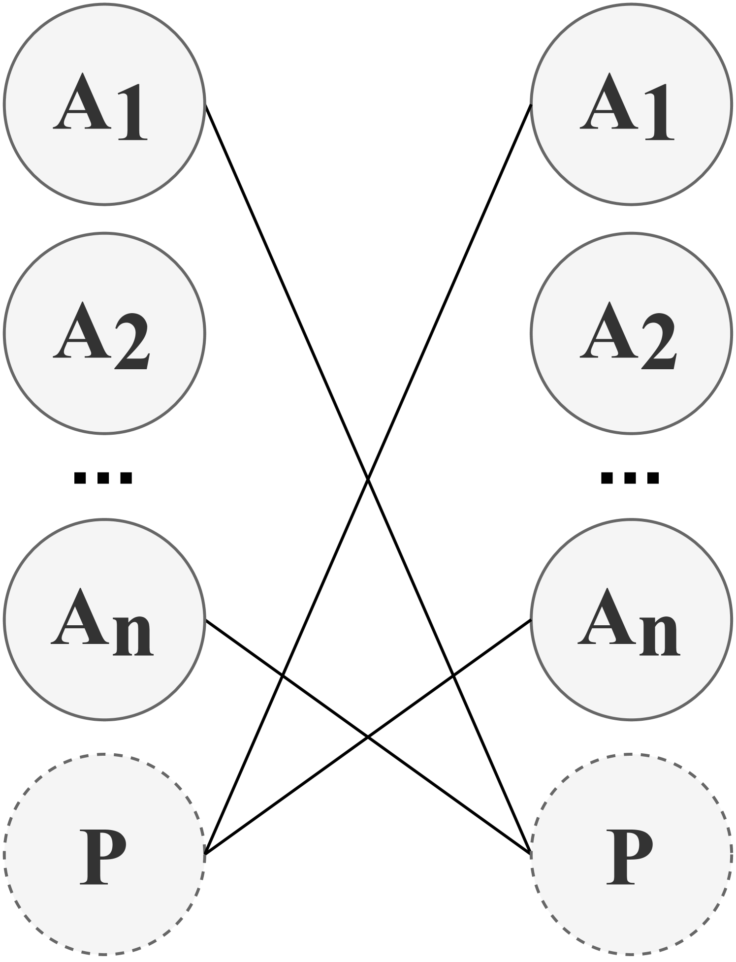
The image displays a schematic diagram representing a bipartite relationship or mapping between two sets of nodes. The diagram is composed of two vertical columns of circular nodes, with lines indicating specific connections between nodes from the left column to the right column. The visual style is minimal, using black lines and text on a light gray background.
### Components/Axes
* **Structure:** Two parallel vertical columns of nodes.
* **Left Column Nodes (Top to Bottom):**
* A solid-outlined circle labeled **A1**.
* A solid-outlined circle labeled **A2**.
* An ellipsis (**...**) indicating a sequence of omitted nodes.
* A solid-outlined circle labeled **An**.
* A dashed-outlined circle labeled **P**.
* **Right Column Nodes (Top to Bottom):**
* A solid-outlined circle labeled **A1**.
* A solid-outlined circle labeled **A2**.
* An ellipsis (**...**) indicating a sequence of omitted nodes.
* A solid-outlined circle labeled **An**.
* A dashed-outlined circle labeled **P**.
* **Connections (Lines):** Four straight black lines connect specific nodes between the columns:
1. From left **A1** to right **An**.
2. From left **An** to right **A1**.
3. From left **P** to right **A2**.
4. From right **P** to left **A2**.
### Detailed Analysis
The diagram defines a specific, non-sequential mapping between two identical sets of elements {A1, A2, ..., An, P}. The connections form a cross-pattern:
* The first element (A1) of the left set maps to the last 'A' element (An) of the right set.
* The last 'A' element (An) of the left set maps to the first element (A1) of the right set.
* The special element P on the left maps to the second element (A2) on the right.
* The special element P on the right maps to the second element (A2) on the left.
The ellipsis (...) between A2 and An in both columns signifies that this is a generalized diagram for an arbitrary number 'n' of 'A'-type elements. The dashed outline for the 'P' nodes visually distinguishes them from the solid-outlined 'A' nodes, suggesting 'P' may represent a different category, a placeholder, or a parameter.
### Key Observations
1. **Symmetry and Inversion:** The connections between A1 and An are perfectly inverted (left A1 → right An, left An → right A1).
2. **Asymmetric Role of P:** The 'P' nodes are involved in a different connection pattern (to/from A2) compared to the 'A' nodes.
3. **Visual Distinction:** The use of a dashed outline for 'P' is a critical visual cue indicating a different status or property.
4. **Generalized Structure:** The ellipsis confirms the diagram is a template, not a depiction of a fixed, small set.
### Interpretation
This diagram is an abstract representation of a **specific permutation or mapping rule** between two ordered sets. It is likely used in contexts such as:
* **Mathematics/Computer Science:** Illustrating a specific bijective function, a permutation cycle, or a network routing pattern. The cross-connection of A1 and An is a classic "swap" operation.
* **Systems Theory or Logic:** Modeling a relationship where certain elements (the 'A's) follow one set of rules (the cross-swap), while a distinct element ('P') follows a different rule (mapping to A2). The dashed outline for 'P' emphasizes its unique role in the system.
* **Algorithm Design:** Could represent a step in an algorithm where specific indices are swapped and a special value is handled separately.
The diagram's power lies in its abstraction. It conveys a precise relational structure without specifying the concrete nature of the 'A' or 'P' elements, making it applicable to various fields where such mapping logic is relevant. The key takeaway is the defined, non-sequential correspondence between the two sets, highlighted by the visual distinction of the 'P' element.