\n
## Diagram: FloD-3DGS Pipeline
### Overview
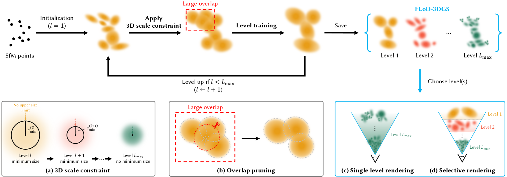
This diagram illustrates the pipeline for FloD-3DGS (likely a 3D reconstruction or rendering technique). It depicts a multi-level approach starting from SfM (Structure from Motion) points, applying scale constraints, level training, and ultimately rendering at different levels of detail. The diagram is structured as a flow chart with several sub-diagrams explaining specific steps.
### Components/Axes
The diagram consists of the following main components:
* **Initialization:** Starting point with SfM points.
* **3D Scale Constraint:** Applying a 3D scale constraint to the points.
* **Level Training:** Iterative training process with large overlap.
* **FloD-3DGS Levels:** Multiple levels of detail (Level 1 to Level Lmax).
* **Level Up:** Condition for increasing the level (l < Lmax).
* **Rendering:** Single-level and selective rendering options.
* **Sub-diagrams (a), (b), (c), (d):** Detailed explanations of specific steps.
### Detailed Analysis or Content Details
The diagram shows a flow from left to right.
1. **Initialization:** A collection of SfM points (represented as black dots) is the starting point.
2. **3D Scale Constraint:** The points are transformed into a 3D point cloud. A red dashed box indicates the application of a 3D scale constraint.
3. **Level Training:** The point cloud undergoes level training, indicated by a larger red dashed box. The point cloud appears to become denser during this stage.
4. **FloD-3DGS Levels:** The trained point cloud is saved and organized into multiple levels (Level 1, Level 2, ... Level Lmax). Each level is represented by a differently colored point cloud (orange, red, and lighter shades). The levels are enclosed in a curly brace.
5. **Level Up:** A feedback loop indicates that the level is incremented (l ← l + 1) if the current level (l) is less than the maximum level (Lmax).
6. **Rendering:** Two rendering options are presented: single-level rendering and selective rendering.
**Sub-diagram (a) - 3D Scale Constraint:**
* Shows three circles representing Level l, Level l+1, and Level Lmax.
* Level l has a "minimum size" constraint.
* Level l+1 has a "minimum size" constraint.
* Level Lmax has "no upper size limit".
* Text: "No upper size limit"
**Sub-diagram (b) - Overlap Pruning:**
* Shows a point cloud within a dashed circle representing "Large overlap".
* An arrow indicates the pruning of points, resulting in a sparser point cloud.
* Text: "Large overlap"
**Sub-diagram (c) - Single Level Rendering:**
* Shows a green cone-shaped rendering of points from Level Lmax.
* Text: "Single level rendering"
* Text: "Level Lmax"
**Sub-diagram (d) - Selective Rendering:**
* Shows a rendering with points from Level 1 (blue) and Level Lmax (red).
* Text: "Selective rendering"
* Text: "Level 1"
* Text: "Level Lmax"
### Key Observations
* The process is iterative, with level training and level up steps.
* The diagram emphasizes the creation of multiple levels of detail for efficient rendering.
* Overlap pruning is used to optimize the point cloud.
* The rendering options allow for both simple and complex visualizations.
* The scale constraint is applied at the beginning of the process.
### Interpretation
The diagram describes a hierarchical 3D reconstruction and rendering pipeline. The FloD-3DGS technique appears to leverage multiple levels of detail to balance rendering speed and quality. The initial SfM points are refined through scale constraints and level training, resulting in a multi-resolution representation. The overlap pruning step suggests an optimization strategy to reduce computational cost. The rendering options provide flexibility in visualizing the reconstructed scene, allowing for either a simplified single-level view or a more detailed selective rendering. The sub-diagrams provide insights into the specific mechanisms used in each step, such as the scale constraint and overlap pruning. The diagram suggests a robust and efficient approach to 3D reconstruction and rendering, particularly suitable for large-scale scenes. The use of "l" and "Lmax" suggests a mathematical formulation underlying the level selection process. The diagram does not provide numerical data, but rather a conceptual overview of the pipeline.