## Diagram: 64-bit Operation Diagram
### Overview
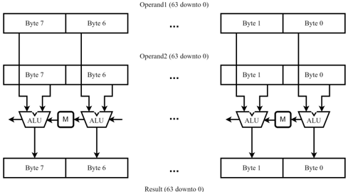
The image is a diagram illustrating a 64-bit operation, likely within a processor or similar digital system. It shows how two 64-bit operands are processed byte-by-byte using Arithmetic Logic Units (ALUs) and an 'M' component, presumably representing memory or a multiplexer. The diagram highlights the parallel processing of bytes to produce a 64-bit result.
### Components/Axes
* **Operands:**
* Operand1 (63 downto 0): Represents the first 64-bit input. It is divided into bytes labeled Byte 7, Byte 6, ..., Byte 1, Byte 0.
* Operand2 (63 downto 0): Represents the second 64-bit input, also divided into bytes labeled Byte 7, Byte 6, ..., Byte 1, Byte 0.
* **Processing Units:**
* ALU: Arithmetic Logic Unit, the core processing element.
* M: A component labeled 'M', likely representing memory or a multiplexer. It sits between the ALUs.
* **Result:**
* Result (63 downto 0): The 64-bit output of the operation, divided into bytes labeled Byte 7, Byte 6, ..., Byte 1, Byte 0.
* **Connectors:**
* Lines with arrowheads indicate the flow of data between components.
### Detailed Analysis
The diagram can be broken down into two identical halves, processing bytes 7-6 and bytes 1-0 respectively.
* **Top:** Two input operands, Operand1 and Operand2, each 64 bits wide, are shown. Each operand is divided into 8 bytes (Byte 7 to Byte 0).
* **Middle:** Each corresponding byte from Operand1 and Operand2 is fed into an ALU. The output of the ALUs is then connected to the 'M' component.
* **Bottom:** The output of the 'M' component and the ALUs combine to form the Result (63 downto 0), which is also divided into 8 bytes (Byte 7 to Byte 0).
Specifically:
* Byte 7 of Operand1 and Byte 7 of Operand2 are inputs to an ALU.
* Byte 6 of Operand1 and Byte 6 of Operand2 are inputs to an ALU.
* Byte 1 of Operand1 and Byte 1 of Operand2 are inputs to an ALU.
* Byte 0 of Operand1 and Byte 0 of Operand2 are inputs to an ALU.
The outputs of the ALUs are connected to the 'M' component. The final result is constructed from the outputs of the ALUs and the 'M' component.
### Key Observations
* The diagram suggests a parallel processing architecture where bytes of the operands are processed simultaneously.
* The 'M' component likely plays a role in handling carry or other inter-byte dependencies.
* The "63 downto 0" notation indicates that the most significant bit is bit 63, and the least significant bit is bit 0.
### Interpretation
The diagram illustrates a 64-bit operation performed by breaking down the operands into bytes and processing them in parallel using ALUs. The 'M' component likely handles carry propagation or other inter-byte dependencies to ensure the correct result. This architecture allows for faster processing compared to a serial approach. The diagram is a high-level representation and does not specify the exact nature of the operation performed by the ALUs or the function of the 'M' component.