## Block Diagram: Audio Processing Neural Network Architecture
### Overview
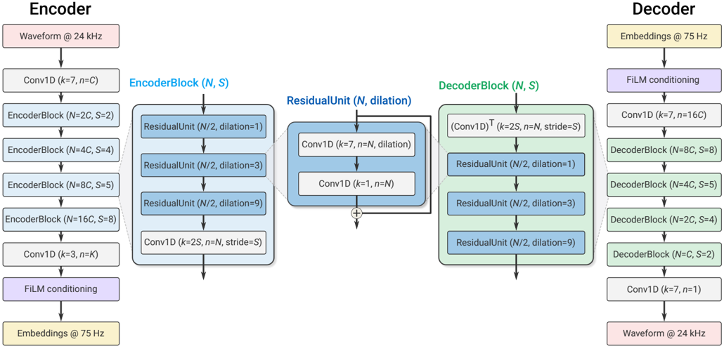
The diagram illustrates a neural network architecture for audio processing, featuring an encoder-decoder structure with residual units and film conditioning. The system processes audio waveforms at 24 kHz, with embeddings at 75 Hz, and includes multiple convolutional and residual blocks with specific dilation patterns.
### Components/Axes
**Key Components:**
1. **Encoder Section (Left Side)**
- Input: Waveform @ 24 kHz
- Initial Layer: Conv1D (k=7, n=C)
- EncoderBlocks:
- EncoderBlock (N=2C, S=2)
- EncoderBlock (N=4C, S=4)
- EncoderBlock (N=8C, S=5)
- EncoderBlock (N=16C, S=8)
- Final Encoder Layer: Conv1D (k=3, n=K)
- Film Conditioning: Embeddings @ 75 Hz
2. **Residual Unit (Center)**
- Structure:
- ResidualUnit (N/2, dilation=1)
- ResidualUnit (N/2, dilation=3)
- ResidualUnit (N/2, dilation=9)
- Core Operations:
- Conv1D (k=7, n=K)
- Conv1D (k=3, n=N)
3. **Decoder Section (Right Side)**
- Input: Embeddings @ 75 Hz
- Film Conditioning
- DecoderBlocks (reverse order of encoder):
- DecoderBlock (N=16C, S=8)
- DecoderBlock (N=8C, S=5)
- DecoderBlock (N=4C, S=4)
- DecoderBlock (N=2C, S=2)
- Final Output: Waveform @ 24 kHz
**Parameter Notation:**
- `k`: Kernel size
- `n`: Number of channels
- `C`: Channel multiplier
- `S`: Stride
- `K`: Final channel count
- `N`: Base channel count
### Detailed Analysis
**Encoder Flow:**
1. Starts with 24 kHz waveform input
2. Initial Conv1D (k=7, n=C) reduces temporal resolution
3. Four EncoderBlocks progressively increase channel count (2C→4C→8C→16C) while reducing temporal resolution via stride (S=2→4→5→8)
4. Final Conv1D (k=3, n=K) prepares for residual unit input
**Residual Unit:**
- Implements dilated convolutions with increasing dilation factors (1→3→9)
- Core operations:
- 7x7 Conv1D (k=7, n=K) with dilation=1
- 3x3 Conv1D (k=3, n=N) with dilation=3
- 1x1 Conv1D (k=1, n=N) with dilation=9
- Output combines all residual paths
**Decoder Flow:**
1. Starts with 75 Hz embeddings
2. Film conditioning adapts normalization parameters
3. Four DecoderBlocks reverse the encoder process:
- Channel reduction (16C→8C→4C→2C)
- Temporal upsampling via stride (S=8→5→4→2)
4. Final Conv1D (k=7, n=1) produces 24 kHz output waveform
### Key Observations
1. **Symmetric Architecture**: Encoder/Decoder mirror each other with reversed channel counts and strides
2. **Dilation Pattern**: Residual unit uses 1→3→9 dilation for multi-scale feature capture
3. **Channel Progression**:
- Encoder: C→2C→4C→8C→16C
- Decoder: 16C→8C→4C→2C
4. **Temporal Resolution**:
- Encoder: 24 kHz → 12 kHz → 6 kHz → 3 kHz → 1.5 kHz
- Decoder: 1.5 kHz → 3 kHz → 6 kHz → 12 kHz → 24 kHz
5. **Film Conditioning**: 75 Hz embeddings modulate network behavior throughout
### Interpretation
This architecture appears to be a modified U-Net for audio processing, combining:
- **Residual Learning**: Through skip connections in encoder/decoder
- **Dilated Convolutions**: For capturing long-range dependencies
- **Multi-scale Processing**: Via progressive channel expansion/contraction
- **Conditioning Mechanism**: 75 Hz embeddings likely provide content-specific guidance
The use of 7x7 and 3x3 kernels suggests a focus on capturing both local and global audio features. The 24 kHz input/output indicates standard telephone-quality audio processing, while 75 Hz embeddings might represent prosodic or spectral features for conditioning.