## Diagram: System Flow with Global Fan-Out and Beta Transition
### Overview
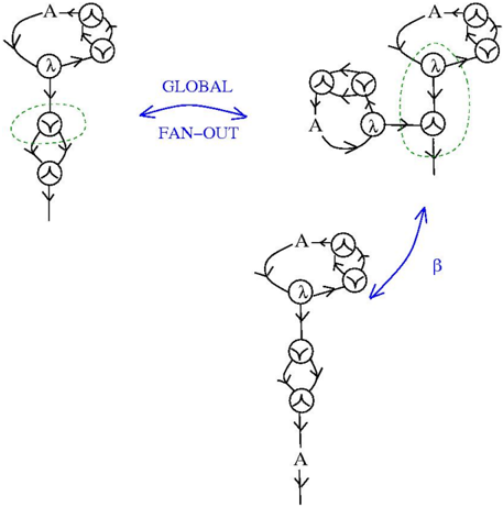
The image depicts a three-part system flow diagram with labeled components and directional arrows. It illustrates transitions between states or processes, emphasizing a "GLOBAL FAN-OUT" mechanism and a "β" transition. The diagrams use standard flowchart notation with loops, arrows, and dashed circles to denote groupings or focus areas.
### Components/Axes
- **Left Diagram**:
- Contains a loop with nodes labeled **A**, **λ**, and **Y**.
- A dashed circle encloses **Y**, suggesting a subgroup or critical component.
- Arrows form a closed loop: **A → λ → Y → A**.
- **Middle Diagram (Global Fan-Out)**:
- Labeled **"GLOBAL FAN-OUT"** with bidirectional arrows.
- Contains nodes **A**, **λ**, and **Y** in a triangular configuration.
- Dashed circles enclose **A** and **Y**, indicating interconnected subgroups.
- Arrows show bidirectional flow between all nodes.
- **Right Diagram**:
- Contains a loop with nodes **A**, **λ**, and **Y**.
- A dashed circle encloses **A** and **Y**, similar to the middle diagram.
- An arrow labeled **β** connects this loop to the bottom diagram.
- **Bottom Diagram**:
- Linear flow with nodes **A**, **λ**, **Y**, and **A** in sequence.
- Arrows indicate unidirectional flow: **A → λ → Y → A**.
### Detailed Analysis
- **Labels**:
- **A**, **λ**, **Y**: Core nodes in all diagrams, likely representing states, processes, or entities.
- **GLOBAL FAN-OUT**: Indicates a distributed or parallelized transition between states.
- **β**: A directional transition between the middle and bottom diagrams.
- **Flow Direction**:
- Left diagram: Closed loop with emphasis on **Y** (dashed circle).
- Middle diagram: Bidirectional flow between all nodes, with **A** and **Y** highlighted.
- Right diagram: Closed loop with **A** and **Y** grouped.
- Bottom diagram: Linear progression ending in a self-loop at **A**.
### Key Observations
1. **Global Fan-Out**: The middle diagram suggests a decentralized or parallelized interaction between **A**, **λ**, and **Y**, with **A** and **Y** as focal points.
2. **β Transition**: The arrow labeled **β** implies a critical or probabilistic shift from the grouped **A/Y** loop to the linear **A→λ→Y→A** sequence.
3. **Dashed Circles**: Used to highlight subgroups (**Y** in the left diagram, **A/Y** in the middle and right diagrams), possibly denoting priority or interdependence.
### Interpretation
This diagram likely models a system with modular components (**A**, **λ**, **Y**) and dynamic interactions. The "GLOBAL FAN-OUT" mechanism may represent load balancing, parallel processing, or distributed state management. The **β** transition could signify a failure mode, optimization step, or probabilistic branching in the workflow.
- **Notable Patterns**:
- **A** appears as a central node in all diagrams, suggesting it is a primary actor or initiator.
- **Y** is consistently grouped (dashed circles), indicating its critical role in transitions.
- The linear bottom diagram contrasts with the bidirectional middle diagram, implying a shift from distributed to sequential processing.
- **Underlying Logic**:
- The use of loops and bidirectional arrows in the middle diagram contrasts with the unidirectional flow in the bottom diagram, hinting at adaptive system behavior.
- The **β** transition may represent a threshold or condition-triggered change in the system’s operational mode.
This structure could apply to computational workflows, network topologies, or process engineering systems where modularity and dynamic transitions are critical.