\n
## Diagram: Interconnect of Voltage Sources and Rectangular Array
### Overview
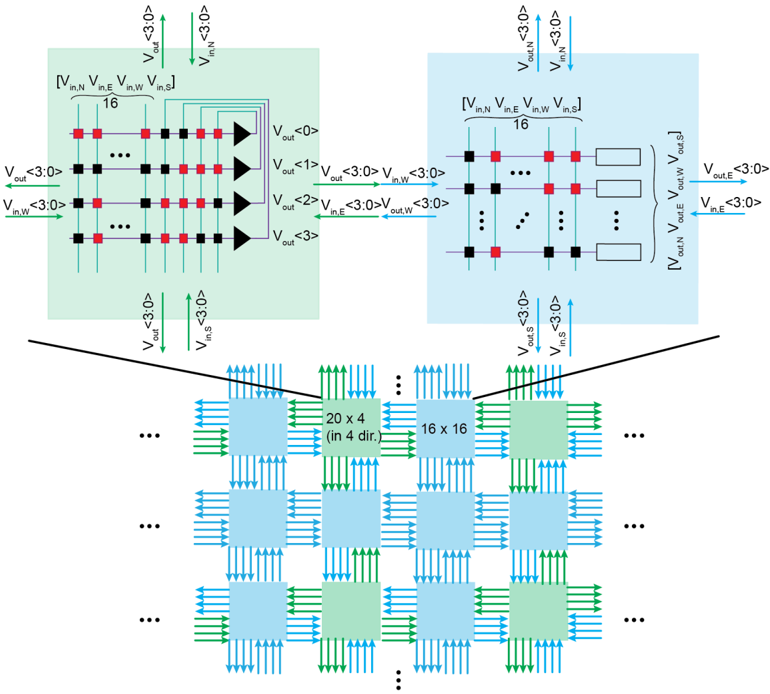
The image depicts a schematic diagram illustrating the interconnection of multiple voltage sources to a rectangular array of elements. The diagram shows a hierarchical structure, starting with individual voltage sources, then a grouping of these sources, and finally their connection to a grid-like array. The diagram appears to represent a power distribution or signal routing scheme.
### Components/Axes
The diagram consists of the following key components:
* **Voltage Sources:** Represented by triangular symbols with input and output terminals labeled with voltage notations (e.g., V<sub>in,N</sub>, V<sub>out</sub>).
* **Interconnections:** Horizontal and vertical lines connecting the voltage sources to the rectangular array. These lines represent electrical connections.
* **Rectangular Array:** A grid of rectangular blocks, presumably representing individual elements or components.
* **Labels:** Various labels indicating voltage names and array dimensions.
* **Ellipsis (...):** Used to indicate continuation of patterns.
The diagram does not have traditional axes like a chart. Instead, it uses spatial arrangement to convey information.
### Detailed Analysis or Content Details
**Top Section (Voltage Source Grouping):**
* A group of voltage sources is shown on the left. Each source has an input (V<sub>in,N</sub>) and an output (V<sub>out</sub>). The subscript 'N' likely denotes a specific source within the group. The voltage notation "<3:0>" appears next to the voltage labels, suggesting a bit width or range of values.
* The voltage sources are connected in a parallel arrangement.
* The grouping is repeated multiple times, indicated by the ellipsis.
* The right side shows a similar grouping, with labels V<sub>in,E</sub>, V<sub>in,S</sub>, V<sub>in,W</sub>, V<sub>out,E</sub>, V<sub>out,S</sub>, V<sub>out,W</sub>. The subscripts E, S, W, and N likely denote East, South, West, and North directions.
* There are labels V<sub><0>out</sub>, V<sub><1>out</sub>, V<sub><2>out</sub>, V<sub><3>out</sub>.
**Bottom Section (Rectangular Array):**
* The rectangular array is composed of multiple blocks.
* The array is labeled "20 x 4 (in dir.)" and "16 x 16". This indicates the dimensions of the array. The "(in dir.)" suggests the 20x4 array is oriented in a specific direction.
* Green arrows point towards the array, representing the input voltages.
* The array is also repeated multiple times, indicated by the ellipsis.
* The output of the array is labeled "out".
**Interconnections:**
* The voltage sources are connected to the array via horizontal and vertical lines.
* The lines are colored red, indicating electrical connections.
* The green arrows represent the direction of voltage flow.
### Key Observations
* The diagram shows a structured approach to distributing voltage to a large array of elements.
* The use of multiple voltage sources suggests a need for redundancy or increased power capacity.
* The array dimensions indicate a significant number of elements.
* The "<3:0>" notation suggests a digital or quantized voltage representation.
* The diagram is highly symmetrical, suggesting a regular pattern of connections.
### Interpretation
The diagram likely represents a power distribution network for an integrated circuit or a similar electronic system. The voltage sources provide power to the rectangular array, which could represent a memory array, a display, or a processing unit. The hierarchical structure allows for efficient distribution of power to a large number of elements. The "<3:0>" notation suggests that the voltages are controlled with a resolution of 4 bits. The symmetry of the diagram indicates a regular and predictable layout, which is common in integrated circuit design. The use of directional labels (N, S, E, W) suggests that the array may have specific orientation requirements. The diagram is a high-level representation and does not provide details about the specific components or their functionality. It focuses on the interconnection scheme and the overall architecture of the system. The ellipsis indicate that the array and voltage source groupings are repeated, suggesting a scalable design.