## Diagram: Protocol Negotiation Process
### Overview
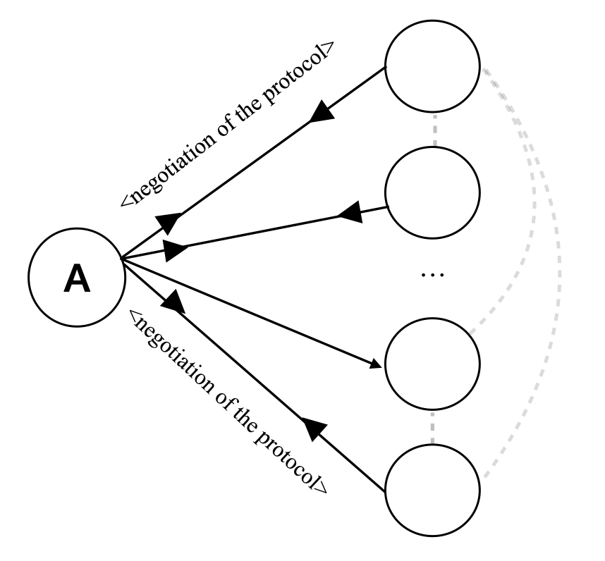
The diagram illustrates a centralized protocol negotiation process involving a primary node (labeled "A") and multiple secondary nodes. Arrows labeled "negotiation of the protocol" indicate directional communication from the central node to peripheral nodes, with a cyclical feedback loop among the peripheral nodes.
### Components/Axes
- **Central Node**: Labeled "A" (positioned at the bottom-left).
- **Peripheral Nodes**: Five unlabeled nodes arranged in a semi-circular pattern around node A.
- **Arrows**:
- Solid black arrows labeled "negotiation of the protocol" (four direct connections from A to peripheral nodes).
- Dashed gray loop connecting peripheral nodes in a clockwise direction (no explicit labels).
- **No numerical axes, scales, or legends present**.
### Detailed Analysis
- **Central Node (A)**: Acts as the initiator of negotiations, with all outgoing arrows originating here.
- **Peripheral Nodes**: Receive input from A and participate in a closed-loop interaction (dashed lines suggest iterative or cyclical communication).
- **Arrow Labels**: All solid arrows share the identical label "negotiation of the protocol," implying uniform communication type.
- **Dashed Loop**: Implies a secondary process (e.g., consensus-building, error correction) among peripheral nodes after initial negotiation.
### Key Observations
1. **Centralized Control**: Node A dominates the process, with no incoming arrows, suggesting it dictates initial protocol terms.
2. **Cyclical Feedback**: The dashed loop indicates ongoing refinement or validation among peripheral nodes post-negotiation.
3. **Uniform Negotiation**: Identical labels on all solid arrows suggest standardized negotiation steps across all connections.
### Interpretation
This diagram models a hierarchical protocol negotiation system where:
- A central authority (A) proposes protocol terms to multiple entities.
- Peripheral nodes engage in iterative dialogue (dashed loop) to resolve conflicts or optimize the protocol.
- The absence of numerical data implies a focus on process flow rather than quantitative metrics (e.g., success rates, latency).
The structure emphasizes **decentralized consensus** after centralized initiation, common in distributed systems or multi-party agreements. The lack of explicit failure states or termination conditions suggests an idealized, continuous negotiation model.