TECHNICAL ASSET FINGERPRINT
ea33b27117cccf3ddd87f51a
Click to view fullscreen
Press ESC or click to close
FOUND IN PAPERS
EXPERT: gemini-2.5-flash-free VERSION 1
RUNTIME: google-free/gemini-2.5-flash
INTEL_VERIFIED
## Diagram: Hierarchical Decomposition with Iterative Process Flow
### Overview
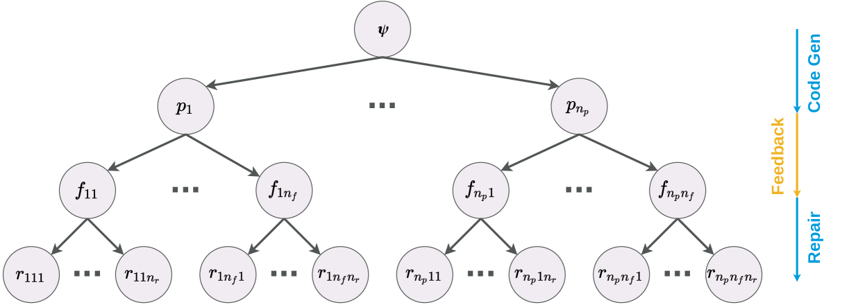
This image presents a hierarchical tree-like diagram illustrating a multi-level decomposition process, accompanied by a vertical process flow description on the right side. The diagram shows a top-down branching structure, where a single root element expands into multiple sub-elements across three subsequent levels, with ellipses indicating omitted intermediate nodes at each branching stage. The right-side labels describe a sequence of operations: "Code Gen", "Feedback", and "Repair", each associated with a specific phase of the hierarchical decomposition.
### Components/Axes
The diagram consists of circular nodes (representing entities or stages) and directed arrows (representing relationships or flow). There are no traditional axes or legends, but the right-side labels serve as a process legend.
**Hierarchical Structure (Nodes and Edges):**
* **Nodes:** All nodes are light grey circles containing black text labels.
* **Level 1 (Root):** A single node at the top-center, labeled "ψ" (psi).
* **Level 2:** Two visible nodes, "p₁" on the left and "p_n_p" on the right. An ellipsis "..." is placed horizontally between them, indicating a series of `n_p` intermediate nodes (p₂, ..., p_n_p-1) are omitted.
* **Level 3:**
* Under "p₁": Two visible nodes, "f₁₁" on the left and "f_1_n_f" on the right. An ellipsis "..." is placed horizontally between them, indicating `n_f` intermediate nodes (f₁₂, ..., f_1_n_f-1) are omitted.
* Under "p_n_p": Two visible nodes, "f_n_p_1" on the left and "f_n_p_n_f" on the right. An ellipsis "..." is placed horizontally between them, indicating `n_f` intermediate nodes (f_n_p_2, ..., f_n_p_n_f-1) are omitted.
* **Level 4 (Leaf Nodes):**
* Under "f₁₁": Two visible nodes, "r₁₁₁" on the left and "r_1_1_n_r" on the right. An ellipsis "..." is placed horizontally between them, indicating `n_r` intermediate nodes (r₁₁₂, ..., r_1_1_n_r-1) are omitted.
* Under "f_1_n_f": Two visible nodes, "r_1_n_f_1" on the left and "r_1_n_f_n_r" on the right. An ellipsis "..." is placed horizontally between them, indicating `n_r` intermediate nodes (r_1_n_f_2, ..., r_1_n_f_n_r-1) are omitted.
* Under "f_n_p_1": Two visible nodes, "r_n_p_1_1" on the left and "r_n_p_1_n_r" on the right. An ellipsis "..." is placed horizontally between them, indicating `n_r` intermediate nodes (r_n_p_1_2, ..., r_n_p_1_n_r-1) are omitted.
* Under "f_n_p_n_f": Two visible nodes, "r_n_p_n_f_1" on the left and "r_n_p_n_f_n_r" on the right. An ellipsis "..." is placed horizontally between them, indicating `n_r` intermediate nodes (r_n_p_n_f_2, ..., r_n_p_n_f_n_r-1) are omitted.
* **Edges:** All connections are dark grey directed arrows pointing downwards, indicating a flow or derivation from a parent node to its child nodes.
**Process Flow Labels (Right Side):**
Positioned vertically along the right edge of the diagram, these labels describe a process sequence.
* **Top:** A vertical blue arrow pointing downwards, labeled "Code Gen" in blue text. This arrow spans vertically, aligning with the first two levels of the hierarchical diagram (from "ψ" down to the "f" nodes).
* **Middle:** A vertical orange arrow pointing downwards, labeled "Feedback" in orange text. This arrow is positioned below "Code Gen" and aligns vertically with the transition from the "f" nodes to the "r" nodes in the hierarchical diagram.
* **Bottom:** A vertical blue arrow pointing downwards, labeled "Repair" in blue text. This arrow is positioned below "Feedback" and aligns vertically with the bottom-most "r" nodes in the hierarchical diagram.
### Detailed Analysis
The diagram illustrates a four-level hierarchical decomposition.
1. **Level 1 to Level 2:** The root node "ψ" branches into a set of `n_p` nodes, represented by "p₁" through "p_n_p". This indicates a primary decomposition or generation step.
2. **Level 2 to Level 3:** Each "p_i" node further branches into a set of `n_f` nodes, represented by "f_i1" through "f_i_n_f". This signifies a secondary decomposition or feature extraction step for each 'p' component.
3. **Level 3 to Level 4:** Each "f_ij" node then branches into a set of `n_r` nodes, represented by "r_ij1" through "r_ij_n_r". This represents a tertiary decomposition, possibly leading to specific results or repair actions.
The process flow labels on the right provide a contextual interpretation of these hierarchical levels:
* The "Code Gen" phase (blue arrow) corresponds to the initial top-down decomposition from "ψ" to the "p" nodes and then to the "f" nodes. This suggests that the generation of code or a primary structure occurs in these initial stages.
* The "Feedback" phase (orange arrow) aligns with the transition from the "f" nodes to the "r" nodes. This implies that after the initial generation (f-nodes), an evaluation or feedback mechanism is applied, leading to the "r" nodes.
* The "Repair" phase (blue arrow) aligns with the "r" nodes themselves, or the final output derived from them. This suggests that the "r" nodes represent repair actions or refined outputs based on the feedback received.
The consistent downward direction of all arrows in both the hierarchy and the process flow indicates a sequential, top-down progression. The use of subscripts `n_p`, `n_f`, and `n_r` implies that the number of branches at each level can vary, making the decomposition flexible.
### Key Observations
* The diagram represents a recursive or iterative decomposition process, where a high-level entity is broken down into increasingly granular components.
* The ellipsis notation "..." is used extensively to denote omitted intermediate nodes, implying a generalizable structure rather than a fixed number of branches.
* The right-side labels provide a functional context to the hierarchical levels, mapping stages of decomposition to phases of a process (Code Generation, Feedback, Repair).
* The color coding of the process flow labels (blue for "Code Gen" and "Repair", orange for "Feedback") might distinguish between primary forward actions (blue) and an intermediate evaluative or corrective step (orange).
### Interpretation
This diagram likely illustrates a conceptual model for an automated system or a problem-solving methodology, possibly in the domain of software engineering, design automation, or AI-driven development.
* **ψ (Psi):** Could represent the initial high-level problem statement, a system specification, or a desired outcome.
* **p (Parameters/Parts/Processes):** The first level of decomposition (p₁ to p_n_p) suggests breaking down the initial problem into major parameters, components, or parallel processes.
* **f (Features/Functions/Factors):** The second level of decomposition (f_i1 to f_i_n_f) indicates a further breakdown of each parameter/part into specific features, functions, or influencing factors.
* **r (Results/Repairs/Refinements):** The final level (r_ij1 to r_ij_n_r) represents the most granular elements, which, in the context of the right-side labels, are likely specific results, repair actions, or refinements derived from the features.
The process flow on the right suggests an iterative or cyclical approach:
1. **Code Gen:** The initial phase involves generating a solution or a system structure, represented by the decomposition from "ψ" down to the "f" nodes. This could be an automated code generation step, a design synthesis, or an initial hypothesis formulation.
2. **Feedback:** Once the initial generation is complete (at the "f" node level), a feedback mechanism is engaged. This implies evaluation, testing, or analysis of the generated components/features. This feedback then informs the next stage.
3. **Repair:** Based on the feedback, specific "repair" actions or refinements are performed, represented by the "r" nodes. This suggests an iterative refinement loop where the generated solution is adjusted or corrected to meet requirements or improve performance.
The overall interpretation is a system that generates a solution through hierarchical decomposition, evaluates it, and then iteratively repairs or refines it based on feedback. The blue arrows for "Code Gen" and "Repair" might signify the primary forward progression of the system, while the orange "Feedback" arrow highlights a critical intermediate step for evaluation and guidance. This model emphasizes a structured, top-down approach to problem-solving with built-in mechanisms for quality assurance and improvement.
DECODING INTELLIGENCE...