\n
## Diagram: Stroke Diagnosis Procedure
### Overview
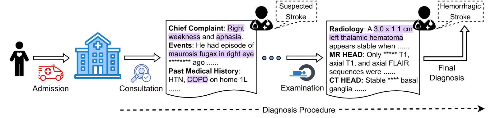
This diagram illustrates the procedure for diagnosing a stroke, starting from patient admission and culminating in a final diagnosis. It depicts a sequential flow of events, including patient presentation, consultation, examination, and radiological findings. The diagram uses icons to represent stages and text boxes to provide details.
### Components/Axes
The diagram is structured horizontally, with stages labeled as:
* **Admission:** Represented by a person icon.
* **Consultation:** Represented by a hospital building icon and a doctor with a stethoscope icon.
* **Examination:** Represented by an eye icon.
* **Final Diagnosis:** Represented by a brain icon.
A dashed line labeled "Diagnosis Procedure" runs horizontally across the bottom, indicating the flow of the process. Text boxes are positioned above each stage, providing details. Dotted lines with rounded rectangles indicate potential diagnoses at intermediate stages.
### Detailed Analysis or Content Details
1. **Admission:**
* No specific data points, but the stage is labeled "Admission".
2. **Consultation:**
* **Chief Complaint:** Right weakness and aphasia.
* **Events:** He had an episode of *maurosis fugax* in right eye ago. (The exact time "ago" is obscured by asterisks).
* **Past Medical History:** HTN, COPD on home 1L (likely referring to 1 liter of oxygen).
3. **Suspected Stroke (Intermediate Diagnosis):**
* Labeled as "Suspected Stroke" within a dotted rounded rectangle.
4. **Examination:**
* **Radiology:** A 3.0 x 1.1 cm left thalamic hematoma appears stable when…
* **MR HEAD:** Only T1, axial T1, and axial FLAIR sequences were…
* **CT HEAD:** Stable basal ganglia…
5. **Hemorrhagic Stroke (Final Diagnosis):**
* Labeled as "Hemorrhagic Stroke" within a dotted rounded rectangle.
6. **Diagnosis Procedure:**
* The dashed line at the bottom is labeled "Diagnosis Procedure".
### Key Observations
* The diagram shows a clear progression from initial symptoms to a final diagnosis.
* The size of the left thalamic hematoma is quantified as 3.0 x 1.1 cm.
* The diagram highlights the use of both MR and CT imaging in the diagnostic process.
* The time frame for the "*maurosis fugax*" event is obscured, limiting the information available.
* The phrases following "Radiology:", "MR HEAD:", and "CT HEAD:" are incomplete, indicated by ellipses.
### Interpretation
The diagram illustrates a typical diagnostic pathway for a stroke. The patient presents with symptoms (right weakness and aphasia), undergoes consultation to gather medical history and assess symptoms, then proceeds to examination including radiological imaging (MR and CT scans). The initial suspicion of a stroke is refined through imaging, leading to a final diagnosis of hemorrhagic stroke. The hematoma size provides a quantifiable measure of the stroke's severity. The incomplete phrases suggest that further details regarding the imaging findings and the patient's condition are available but not fully presented in this diagram. The diagram emphasizes the importance of a systematic approach to stroke diagnosis, utilizing both clinical assessment and advanced imaging techniques.