## Diagram: GPU Memory Hierarchy and Execution Flow
### Overview
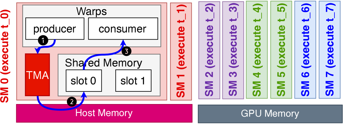
This diagram illustrates the memory hierarchy and execution flow in a GPU computing system. It depicts the interaction between Host Memory, Shared Memory, GPU Memory, and execution stages (t_0 to t_7). Key components include a Transactional Memory Array (TMA), Warps (producer/consumer), and Shared Memory slots. The diagram uses color-coded sections to differentiate memory types and execution phases.
### Components/Axes
1. **Host Memory**: Pink section at the bottom, labeled "Host Memory."
2. **Shared Memory**: Gray section above Host Memory, labeled "Shared Memory" with two slots (slot 0 and slot 1).
3. **GPU Memory**: Gray section on the right, labeled "GPU Memory."
4. **Warps**: Top-left section labeled "Warps," containing "producer" and "consumer" blocks.
5. **TMA**: Red block connected to Shared Memory, labeled "TMA."
6. **Execution Stages**: Vertical timeline on the right with seven stages (t_0 to t_7), color-coded:
- **t_0**: Red (SM 0)
- **t_1**: Pink (SM 1)
- **t_2–t_3**: Purple (SM 2–3)
- **t_4–t_5**: Green (SM 4–5)
- **t_6–t_7**: Blue (SM 6–7)
7. **Arrows**: Blue arrows indicate data flow between components.
### Detailed Analysis
- **Host Memory**: Serves as the source for data transfers, connected to Shared Memory via TMA.
- **Shared Memory**: Acts as an intermediate buffer between Host Memory and GPU Memory. Contains two slots (slot 0 and slot 1) for temporary data storage.
- **TMA**: Facilitates data movement between Host Memory and Shared Memory, highlighted in red.
- **Warps**: Represent parallel processing units. The "producer" writes data to Shared Memory, while the "consumer" reads from it.
- **Execution Stages**: Sequential phases (t_0 to t_7) are color-coded to indicate progression through the GPU pipeline. Each stage corresponds to a specific memory type (SM 0–7).
### Key Observations
- **Color Coding**:
- Red (t_0) and pink (t_1) represent early execution stages tied to Host/Shared Memory.
- Purple (t_2–t_3), green (t_4–t_5), and blue (t_6–t_7) indicate later stages in GPU Memory.
- **Data Flow**:
- Data moves from Host Memory → TMA → Shared Memory → Warps (producer/consumer) → GPU Memory.
- Arrows suggest bidirectional communication between Shared Memory and Warps.
- **Execution Parallelism**:
- Multiple execution stages (t_0–t_7) imply concurrent processing across GPU cores.
### Interpretation
This diagram models a GPU's memory hierarchy and execution pipeline, emphasizing data movement and parallelism. The TMA acts as a bridge between Host and Shared Memory, optimizing data transfers. Warps enable parallel producer-consumer operations within Shared Memory, while the color-coded execution stages reflect the GPU's phased processing of data. The absence of numerical values suggests this is a conceptual model rather than a performance benchmark. The system highlights the importance of efficient memory management in GPU computing, with Shared Memory serving as a critical intermediate layer for reducing latency between Host and GPU Memory.