TECHNICAL ASSET FINGERPRINT
eca4f3d44d3cfc54a3971b2c
Click to view fullscreen
Press ESC or click to close
FOUND IN PAPERS
EXPERT: gemini-2.5-flash-free VERSION 1
RUNTIME: google-free/gemini-2.5-flash
INTEL_VERIFIED
## Diagram: Iterative Code Model Refinement with Feedback
### Overview
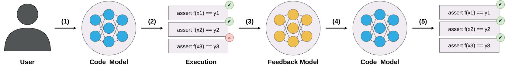
This diagram illustrates a five-step iterative process for refining a "Code Model" based on execution feedback. It begins with a "User" interacting with an initial "Code Model," proceeds through an "Execution" phase where assertions are tested, uses a "Feedback Model" to learn from failures, updates the "Code Model," and concludes with a successful re-execution of the assertions.
### Components/Axes
The diagram is structured horizontally, showing a left-to-right flow of components and processes.
* **User**: Located on the far left, represented by a dark grey silhouette icon of a person's head and shoulders. Labeled "User" directly below the icon.
* **Code Model (Initial)**: Positioned to the right of the "User." It is represented by a light grey circular container enclosing a network of seven interconnected blue circular nodes. The nodes are arranged with three on the left, one in the center, and three on the right, with lines connecting the left nodes to the center, and the center to the right nodes, forming a small, layered network structure. Labeled "Code Model" directly below the circle.
* **Execution (Initial)**: Located to the right of the initial "Code Model." This component consists of three stacked, light grey rectangular blocks, each representing an assertion.
* Top block: "assert f(x1) == y1" with a green checkmark icon on its right edge.
* Middle block: "assert f(x2) == y2" with a green checkmark icon on its right edge.
* Bottom block: "assert f(x3) == y3" with a red 'x' icon on its right edge.
Labeled "Execution" directly below the stacked blocks.
* **Feedback Model**: Positioned to the right of the initial "Execution" phase. It is represented by a light grey circular container enclosing a network of seven interconnected orange circular nodes. The internal structure of nodes and connections is identical to the "Code Model" but with orange nodes. Labeled "Feedback Model" directly below the circle.
* **Code Model (Refined)**: Positioned to the right of the "Feedback Model." This component is visually identical to the initial "Code Model," featuring a light grey circular container with seven interconnected blue circular nodes. Labeled "Code Model" directly below the circle.
* **Execution (Final)**: Located on the far right, to the right of the refined "Code Model." This component also consists of three stacked, light grey rectangular blocks, identical in text to the initial "Execution" blocks.
* Top block: "assert f(x1) == y1" with a green checkmark icon on its right edge.
* Middle block: "assert f(x2) == y2" with a green checkmark icon on its right edge.
* Bottom block: "assert f(x3) == y3" with a green checkmark icon on its right edge.
### Detailed Analysis
The diagram illustrates a sequential process through five numbered steps, indicated by black arrows:
1. **Step (1)**: An arrow points from the "User" to the initial "Code Model." This signifies the user providing input or initiating the "Code Model."
2. **Step (2)**: An arrow points from the initial "Code Model" to the "Execution" blocks. This indicates the "Code Model" is being executed or tested.
* During this initial "Execution," two assertions pass: "assert f(x1) == y1" and "assert f(x2) == y2", indicated by green checkmarks.
* One assertion fails: "assert f(x3) == y3", indicated by a red 'x'.
3. **Step (3)**: An arrow points from the initial "Execution" blocks (specifically, implying the results of the execution) to the "Feedback Model." This suggests that the execution results, particularly the failure, are fed into the "Feedback Model." The "Feedback Model" is visually distinct with orange nodes, implying a different state or function compared to the "Code Model."
4. **Step (4)**: An arrow points from the "Feedback Model" to the refined "Code Model." This indicates that the "Feedback Model" processes the feedback and uses it to update or refine the "Code Model." The "Code Model" reverts to its blue-node representation, signifying it's ready for re-execution.
5. **Step (5)**: An arrow points from the refined "Code Model" to the final "Execution" blocks. This signifies the refined "Code Model" is being executed again.
* In this final "Execution," all three assertions pass: "assert f(x1) == y1", "assert f(x2) == y2", and "assert f(x3) == y3", all indicated by green checkmarks.
### Key Observations
* The process is cyclical and iterative, demonstrating a feedback loop for improvement.
* The "Code Model" is initially imperfect, as evidenced by one failed assertion in the first "Execution."
* The "Feedback Model" (orange nodes) acts as an intermediary step, processing the results of the initial execution to inform the refinement of the "Code Model."
* The "Code Model" is successfully refined, as all assertions pass in the subsequent "Execution."
* The visual representation of the "Code Model" (blue nodes) remains consistent before and after refinement, suggesting its core structure is maintained, but its internal logic or parameters have been adjusted. The "Feedback Model" uses a distinct color (orange nodes) to differentiate its role.
### Interpretation
This diagram illustrates a fundamental concept in software development, machine learning, or automated system design: an iterative process of testing, identifying failures, learning from those failures, and applying corrections to improve a system.
The "User" initiates the process, likely by providing requirements or initial code. The "Code Model" represents the system under development, which could be a piece of software, an algorithm, or a machine learning model. The "Execution" phase simulates running the code or model with specific inputs (x1, x2, x3) and checking if the outputs (f(x1), f(x2), f(x3)) match expected values (y1, y2, y3) through assertions.
The initial failure of "assert f(x3) == y3" highlights a defect or an area for improvement in the "Code Model." This failure is then fed into the "Feedback Model." The "Feedback Model" can be interpreted as an automated debugging system, a learning algorithm, or a human review process that analyzes the failure and determines how to modify the "Code Model." The change in node color from blue to orange for the "Feedback Model" visually distinguishes it as a separate, analytical, or learning component.
Finally, the refined "Code Model" (back to blue nodes) is re-executed, and all assertions pass. This demonstrates that the feedback loop successfully identified and corrected the issue, leading to a more robust and correct system. This pattern is crucial for developing reliable systems, especially in domains like AI where models are continuously trained and fine-tuned based on performance metrics and errors. It suggests a self-correcting or self-improving system where failures are not terminal but rather opportunities for learning and refinement.
DECODING INTELLIGENCE...