## Diagram: AIMC Training/Inference Acceleration and ReRAM-Based AI Core Architecture
### Overview
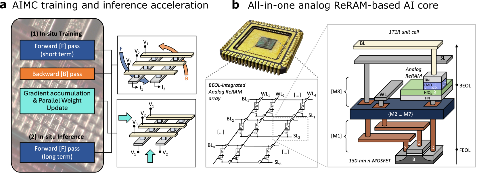
The image presents two technical diagrams:
1. **AIMC Training/Inference Acceleration** (Left): A flowchart showing in-situ training and inference processes with gradient accumulation and weight updates.
2. **All-in-one Analog ReRAM-Based AI Core** (Right): A layered hardware architecture diagram illustrating a BEOL-integrated analog ReRAM array and 1T1R unit cells.
---
### Components/Axes
#### AIMC Training/Inference Acceleration (Left Diagram)
- **Steps**:
- **In-situ Training**:
- Forward pass (F) (short term)
- Backward pass (B)
- Gradient accumulation & Parallel Weight Update
- **In-situ Inference**:
- Forward pass (F) (long term)
- **Components**:
- Voltage sources: V₁, V₂, V₃
- Current sources: I₁, I₂
- Arrows indicate data flow direction (e.g., F → B → Gradient Update → Inference).
- **Color Coding**:
- Blue: Forward pass (F)
- Orange: Backward pass (B)
- Teal: Gradient accumulation & Weight Update
#### ReRAM-Based AI Core (Right Diagram)
- **Key Layers**:
- **BEOL (Bottom Electrode Layer)**:
- Analog ReRAM array with BL (Bit Line) and SL (Select Line) connections.
- 1T1R unit cells (1 Transistor, 1 Resistor) with BL, SL, and analog ReRAM.
- **Memory Stack**:
- M1–M8 layers (red, blue, green, yellow) with TIN (Titanium Nitride) and CMO (Copper Manganese Oxide) materials.
- **FEOL (Front Electrode Layer)**:
- 130-nm n-MOSFET transistors.
- **Color Coding**:
- Red: M1 layer
- Blue: M2–M7 layers
- Green: M8 layer
- Yellow: BL/SL lines
---
### Detailed Analysis
#### AIMC Training/Inference Acceleration
- **Training Process**:
- Forward pass (F) applies input data (V₁, V₂, V₃) to the system.
- Backward pass (B) propagates errors (I₁, I₂) for gradient calculation.
- Gradient accumulation and parallel weight updates occur simultaneously.
- **Inference Process**:
- Long-term forward pass (F) uses updated weights (V₁, V₂) for predictions.
#### ReRAM-Based AI Core
- **1T1R Unit Cell**:
- BL and SL lines control access to analog ReRAM cells.
- Analog ReRAM acts as both memory and computational element.
- **Material Stack**:
- TIN (Titanium Nitride) and CMO (Copper Manganese Oxide) layers enable resistive switching for analog computation.
- **Layering**:
- M1–M8 layers form a vertical stack, with BEOL at the bottom and FEOL at the top.
---
### Key Observations
1. **AIMC Acceleration**:
- Training and inference are optimized by integrating gradient updates during forward/backward passes.
- Parallel weight updates reduce latency compared to traditional training.
2. **ReRAM Architecture**:
- BEOL integration minimizes area overhead by embedding ReRAM directly with memory layers.
- 1T1R design balances transistor control with resistive memory for energy efficiency.
---
### Interpretation
- **AIMC Training**: The in-situ approach suggests a focus on real-time learning, where weights are updated dynamically during data processing. This could enable faster adaptation to new data without separate training phases.
- **ReRAM Core**: The analog ReRAM array leverages resistive switching for energy-efficient computation, while the 1T1R structure ensures precise control over memory cells. The vertical layering (M1–M8) indicates a compact, high-density design suitable for edge AI applications.
- **Synergy**: The AIMC training methodology likely complements the ReRAM core by enabling rapid weight updates during inference, enhancing overall system responsiveness.
No numerical data or trends are present in the image. The diagrams emphasize architectural design and process flow rather than quantitative metrics.